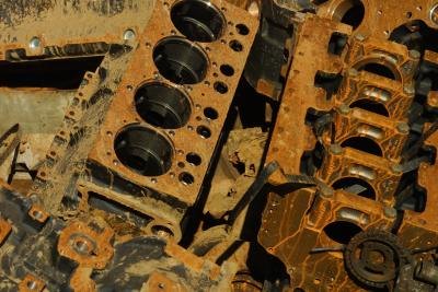
The Cost of Replacing a Cylinder in a Nissan Truck

Friday, February 28, 2014 | Labels: , , , , , , , , | 0 comments |
The Cost of Replacing a Cylinder in a Nissan Truck

Some Nissan models - particularly the ZD30 Nissan patrol, have had a history of serious engine problems over the years, including piston cracks, head cracks and cracked cylinders and engine blocks. Nissan has taken steps to rectify the issues in recent years. If you have a cracked cylinder, that means that the recess in which the piston slides back and forth has become damaged, resulting in the air/fuel mixture leaking out around the piston. If it is the cylinder that is cracked, rather than the piston, you may have to replace the entire engine block.

Diagnosis and Troubleshooting

    A cracked cylinder will generally result in the loss of compression in that one cylinder. You may notice your engine "missing," running poorly and lacking in power. If your car runs at all, you would notice poor acceleration and poor performance on hills. However, there are a number of other issues that could cause this same problem. You may want to check your spark plugs for proper gapping and functioning. Also check your fuel injection system and your head gasket. Each of these items is much less expensive to repair, and would cause similar symptoms, so rule each of these out before replacing the cylinder.

Parts

    If you determine that your engine problems are, in fact, the result of a cracked cylinder, and the crack is too severe to weld shut, you will need to replace the engine block itself. The cost of the engine depends on the year, make and model of your Nissan. Expect to pay between $1,800 and $2,000 for a fully remanufactured engine block. However, you may also be able to find a complete engine in the aftermarket for around a thousand to $1,500, depending on the make and model of your Nissan.

Labor

    Generally, auto mechanic shops have a shop rate prominently posted in the customer service area. This is the hourly rate that the mechanic charges, generally in addition to the diagnostic fee, if any. The mechanic will give you an estimate based on the shop rate, times a multiplier from an industry guide called "The Mitchell Book" that lists how much time it typically takes to do a repair. Expect to pay between 8 and 10 hours of labor charges to do a full engine swap, depending on the make and model of your vehicle, assuming there are no other repairs to do.

Master Cylinder

    It is possible that your mechanic is erring to your master cylinder. The master cylinder converts mechanical energy from your foot pressing down on the brake pedal into hydraulic energy, which is then distributed through the power steering system to your brakes, or to your clutch. You can get a new brake master cylinder for about $100-$120. For clutch master cylinders, expect to pay about $30 to $60 for the part. According to CarsDirect.com, the average cost of a brake master cylinder replacement is $200-$300, including labor.

Continue reading...

How to Stop a Transmission From Slipping

| Labels: , , , , , , | 0 comments |
How to Stop a Transmission From Slipping

When youre driving your car, you tend to get a feel for any mechanical changes in your vehicle that could signal trouble. For example, if you notice that your vehicle is not shifting as smoothly as it used to, it may indicate transmission trouble. When your transmission hesitates or slips, the gears arent moving well. You can often prevent more costly repairs by servicing the transmission.

Instructions

    1

    Your transmission needs to be checked and serviced every 80,000 miles. You can do this by replacing your transmission fluid or flushing it out. Removing the transmission fluid is vital because this ensures that any debris it has accumulated will be removed. When removing the transmission fluid, you will have to remove the transmission pan, drain it, and then replace the filter and fluid.

    2

    When you add or replace your transmission fluid, make sure that you fill it up with the correct amount, according to your vehicle manufacturers manual. The transmission fluid lubricates and allows hydraulic pressure to occur in the transmission gears. If the fluid is too old, it wont be able to provide the necessary lubrication. Check the levels by looking at the transmission gauge. Examine the fluid and note its consistency. It should have a pinkish hue to it. If it has a dark red color, the fluid is should be replaced.

    3

    Transmission additives can help keep your transmission from slipping. Several companies make transmission additives, but you will need to make sure that the additives are compatible with your transmission.

    4

    Keep an eye on our RPM gauge when driving. If RPMs are higher than usual and your vehicle is laboring as it shifts gears, it indicates a transmission problem. Many vehicles made after the year 2000 have a transmission module box in the engine. The codes in this module box can be scanned at an automotive repair shop to give a more definitive answer to what is making your transmission slip.

Continue reading...

How To Change a Toyota Paseos Exhaust

Thursday, February 27, 2014 | Labels: , , , , , , | 0 comments |

The exhaust system in a Toyota Paseo is responsible for carrying the exhaust fumes from the engine to the back of the vehicle. Once fuel has been burned in the engine, it is expelled through the exhaust manifold and into the exhaust system. Over time, the exhaust system will fail primarily due to either rust or corrosion. However, if the exhaust system in your Paseo has been damaged in any way, its time to change it.

Instructions

    1

    Jack up the front of the Toyota Paseo using the front jack point located behind the radiator, and place the jack stands underneath the front pinch welds located on either side of the vehicle.

    2

    Jack up the rear of the vehicle using the rear jack point near the trunk area and place jack stands underneath the rear pinch welds located on either side of the vehicle.

    3

    Loosen and remove the O2 sensor located in the exhaust piping near the catalytic converter. Unplug the electrical wire that is connected to the O2 sensor and then use the O2 sensor removal tool (a socket extension) to turn the O2 sensor counterclockwise.

    4

    Place a jack stand near the catalytic converter to support the exhaust piping. Place another jack stand under the exhaust piping near the rear of the vehicle for additional support.

    5

    Unbolt the exhaust piping from the exhaust manifold.

    6

    Slide the exhaust piping off the rubber hangers that are attached to the body of the vehicle. Since you are replacing the entire exhaust, you dont need to unbolt any of the intermediate pieces.

    7

    Install the new exhaust system. Installation is the reverse of removal.

Continue reading...

1997 Ford SUV Recalls

| Labels: , , , | 0 comments |
1997 Ford SUV Recalls

The lineup of 1997 Ford SUVs included the Expedition and Explorer, which were both part of the recall Ford Motor Company issued involving more than 13 million Ford trucks and SUVs because of tire problems. The 1997 Explorer had an additional 11 recalls, while the 1997 Expedition had eight additional recalls.

Tire Recall

    1997 Ford SUV saw the largest recall for Ford vehicles in several years. More than 13 million Ford vehicles were recalled because of a defect in the Firestone tires that came with the them. The Firestone Wilderness brand tires had problems with the tires separating, causing the tires to fail while driving. If the tires failed at highway speeds, the possibility of an accident occurring were greatly increased, and the National Highway Traffic Safety Administration (NHTSA) had several reports concerning accidents caused by this tire defect.

Expedition Recalls

    The 1997 Ford Expedition saw an additional eight recalls besides the tire recall. Three of the recalls were for exterior-lighting problems. Two of the exterior lighting recalls dealt with improper illumination from the lectors, while the other exterior lighting problem dealt with the daytime running lights (DRL), which illuminated too brightly, affecting oncoming drivers of other vehicles. More than 1.5 million Expeditions and other Ford vehicles were also recalled because of lug-nut problems. The lug nuts installed on these SUVs did not clamp down tight enough, causing movement in the tires during operation. About 500,000 Ford vehicles, including the Expedition, were recalled because of trailer-hitch problems, and almost 900,000 vehicles were recalled because of transmission problems. Another recall dealt with the rear suspension weld, which was missing from the axle track bar, causing the bar to separate from the SUV. The eighth recall was for a problem found in the gear-box shaft. The intermediate yoke of the gear shift was separating from the input shaft of the gear box, preventing the driver from shifting gears.

Explorer Recalls

    The 1997 Explorer had 12 different recalls. One dealt with the massive recall of Ford SUVs and trucks because of the Firestone tires, but second tire recall was issued for the 1997 Ford Explorer for additional tire problems. It involved defective manufacturing of a Firestone tire that was produced at a different plant than the original recalled tire. Four were because of exterior-lighting issues concerning the lectors and daytime running lights, which did not meet safety standards. Four Explorer recalls were because of defects in the speed controls. A cruise control cable was affecting the pulley on the speed control, preventing the speed control from disengaging. Another recall was because a grounding cable was attached to the fuel line. When the Explorer was jump-started with jumper cables, it damaged the fuel line, causing the line to leak gasoline. The other recall dealt with a problem with the front suspension. The sway bar was breaking loose or fracturing for unknown reasons. More than 800,000 Ford vehicles were recalled for this defect, including the 1997 Ford Explorer.

Continue reading...

2000 Jeep Grand Cherokee Laredo Fuel Pump Problems

Wednesday, February 26, 2014 | Labels: , , , , , , , | 0 comments |
2000 Jeep Grand Cherokee Laredo Fuel Pump Problems

Jeep issued a recall on the 2000 Grand Cherokee Laredo in 2005 for fuel pump problems, according to Internet Auto Guide. Not a widespread recall, it only affected a few Laredos, but other fuel pump problems have arisen for some 2000 Jeep owners. The fuel pump pushes gas from the tank through the fuel line and into the engines injectors. Problems with the fuel pump cause little or no fuel to reach the engine, creating multiple problems.

Plastic Grommet Failure

    A plastic grommet on the 2000 Laredo fuel pump module was not compatible with gasoline, which caused the grommet connectors to degrade and allow gasoline to leak out. Since the fuel pump sits near the exhaust system, gasoline leaking out of the fuel pump can land on the exhaust and create a fire hazard. The fuel pump came from a specific manufacturer and only affected 7,291 Chrysler vehicles---including the 2000 Jeep Grand Cherokee Laredo.

Fuel Pump Failure

    According to the website Car Complaints, some 2000 Jeep Grand Cherokee Laredo owners have experienced fuel pump failure. Though no known specific cause for this problem exists as of 2010, gasoline leaking out of the fuel pump can cause it to work harder to push gasoline through the fuel line and possibly burn out. The only correction for this fuel pump problem involves replacing the fuel pump.

CMP Sensor Problems

    The 2000 Jeep Grand Cherokee Laredo has had problems with the camshaft position (CMP) sensor. The Laredo uses the CMP sensor to synchronize the fuel through the fuel pump. When this sensor goes out or operates intermittently, the fuel pump will fail to push gasoline through the fuel line. The vehicle will stall during acceleration, run roughly, jerk or hesitate during operation or achieve low fuel mileage. The CMP sensor requires replacement to correct this fuel pump problem.

Continue reading...

2003 Jetta How to Replace a Cracked Headlight Cover

| Labels: , , , , , , , , | 0 comments |

A cracked headlight cover is a noticeable and common cosmetic problems. While its really not a safety concern, its still something you may want to fix so your Jetta can looks its best. Unfortunately, unlike with other cars, you cannot replace just the cover. Instead you have to replace the entire headlight.

Instructions

    1

    Press down on the snap on the back of the front grill, then remove it.

    2

    Remove the front bumper. Five visible bolts are located where the grill was, and one is behind the grill on the left and right of the bumper. Unscrew them and the four bolts in each wheel well. Once you do that, the bumper will lift right off.

    3

    Unscrew the four screws holding your headlight in. Theres two at the top, and two at the bottom.

    4

    Pull the headlight out.

    5

    Remove the wire plug. It should pull out fairly easily, but if not, press into the hole on the top of the plug with a screwdriver.

    6

    Plug the wire plug into the connector on the back of your new headlight.

    7

    Put the headlight screws back in.

    8

    Slide the bumper back into place and replace all of the bolts.

    9

    Put the front grill back in place, and put the tab you removed firmly back into place.

Continue reading...

History of the Turbocharger

Tuesday, February 25, 2014 | Labels: , , , | 0 comments |
History of the Turbocharger

Engineers and designers who work with internal combustion engines have always sought new ways to produce more power and efficiency. This has driven a great deal of automotive engineering and was the driving force behind the development of the turbocharger. Since its initial application to aircraft engines, the turbocharger has been adapted to different uses and has become an important option for modern automakers.

Origins

    The first turbocharger design earned a patent in 1905 by Swiss engineer Alfred Bchi. It was intended for use on aircraft engines at a time when aviation was a developing field. During World War I, the French military used turbochargers on many of its planes. Turbocharging solved many of the problems associated with high altitude flying by forcing air into the engine, thus negating the effects of the thinner atmosphere and lower oxygen content.
    Throughout the 1920s and 1930s, aviation technology continued to grow and turbochargers became common equipment on most advanced planes. This made it possible to design planes that could fly higher and run more efficiently (theore making them able to stay airborne longer).

Operation

    Turbochargers were developed to solve one of the primary needs of the internal combustion engine: that of feeding air, along with fuel, into the engines combustion chambers. While this air and fuel mixture is compressed during the engines compression cycle, feeding air that is more dense into the engine produces a boost in power. Turbochargers do precisely this, compressing the air in a process known as forced induction. In opposition to superchargers, which were developed later and compress air using energy from the engine itself, turbochargers are powered by the engines exhaust, thus making use of what would otherwise be lost energy.

Turbocharged Cars

    Cars became a natural place for turbochargers to be used once they had been proven on aircraft. As early as 1938, some automakers experimented with turbocharging their diesel engines, to mixed results. Turbochargers remained a mainstay on aircraft engines while only being sporadically offered on cars through much of the 20th century. In the 1950s and 1960s, turbochargers became a popular item for various racing circuits in the United States. The power boost achieved by turbochargers led to regulations of the technology and, in some cases, bans on the use of turbochargers to ensure fair competition.
    In 1962, General Motors became the first American automaker to offer turbochargers on its street cars, offering it on the Chevrolet Corvair and the related Oldsmobile Cutlass.

The Turbo Era

    The late 1970s and early 1980s became known as the "Turbo Era" in Formula 1 racing. This was due to the explosion in the popularity of turbochargers, with many race teams investing a great deal of money into the development of turbochargers that would give them a competitive edge. Some F1 races during the Turbo Era saw an entire field of turbocharged cars in competition. Race officials were quick to regulate turbochargers, placing limits on how much power they could be engineered to provide. Safety became a key concern, and the interest in the technology dropped off sharply. By the mid-1980s, turbochargers were banned altogether and race teams were forced to look elsewhere for improvements to their cars.

Recent History

    Turbochargers received some renewed interest during the Energy Crisis of the 1970s. Besides turning to smaller cars with more modest, fuel efficient engines, automakers began searching for ways to improve efficiency of their existing fleets. Turbocharged cars with four-cylinder engines were often sold alongside V-6 and V-8 models in the 1980s, often with the turbo versions sporting the highest performance ratings.
    Turbochargers also began to appear in other vehicles, such as motorcycles. In the case of motorcycles and sports cars, the light weight of a turbocharger makes it an attractive option for adding power as opposed to the addition of a large, heavy, expensive engine with greater displacement.
    The rise in energy prices in the 2000s only served to continue the advancing trend of turbochargers, seeing them appear in many cars, including small coupes and entry level models.

Continue reading...

How to Clear the Electronic Steering Wheel Code on a BMW

| Labels: , , , , , , , , , , | 0 comments |
How to Clear the Electronic Steering Wheel Code on a BMW

You can clear the electronic steering wheel code on your BMW right from your home garage, saving yourself time and money. The BMW comes standard with an On-Board Diagnostics computer that receives and stores trouble codes sent to it from sensors positioned throughout the vehicle, including from the electronic steering wheel. After repairs have been made, the computer codes need to be reset so any warning lights shut off and the computer can continue to properly monitor the mechanical and electrical functions of the vehicle.

Instructions

    1

    Pop up the hood of your BMW and prop it up with the safety bar.

    2

    Locate the negative battery terminal. Find the clamp on the terminal, which has a nut on top of it. Loosen that nut with a wrench. Slide the clamp off of the negative battery terminal, making sure it doesnt touch metal or the positive terminal.

    3

    Wait 30 minutes while the computer resets itself, thus clearing all codes.

    4

    Reattach the clamp to the negative terminal and tighten the nut. Lower the hood of the car.

    5

    Put the key into the ignition and start the engine. Verify the electronic steering wheel light is shut off the instrument panel.

Continue reading...

How to Move a Car Without Starting It

Monday, February 24, 2014 | Labels: , , , , , , , | 0 comments |
How to Move a Car Without Starting It

You insert your key into your cars ignition to start the engine but nothing happens. Perhaps the battery is dead; maybe the starter is defective. In any case, if your vehicle wont start, you can still move it to another location to jump-start the battery or safely call for help. To move your vehicle without starting it, you will need to shift gears and youll need help pushing the car to the desired location.

Instructions

    1

    Direct one or more strong people to stand ready to push the vehicle to the desired location.

    2

    Depress the brake pedal.

    3

    Insert the key into the ignition and turn it to the "On" position.

    4

    Move the gearshift to "N" or neutral gear

    5

    Steer and brake as necessary while the vehicle is being pushed.

Continue reading...

How to Install a Rivet Nut

| Labels: , , , , , | 0 comments |

A rivet nut contains an internal threaded sleeve surrounded by a thin exterior body. The exterior body dimples to hold the nut in a piece of material. The internal threads remain intact to accept a threaded fastener.

Instructions

    1

    Measure the diameter of the rivet nut.

    2

    Secure a drill bit 1/32 inch larger than the diameter of the nut into the chuck of a drill motor.

    3

    Drill a hole through the base material. Slide a round file through the hole to remove any burrs left by the drill bit.

    4

    Turn a rivet nut clockwise to thread it securely onto the mandrel of a rivet nut tool.

    5

    Slide the rivet nut into the drilled hole.

    6

    Hold the bottom nut of the rivet nut tool with an adjustable wrench. Turn the upper nut clockwise three to four turns with a second adjustable wrench to set the nut in the hole.

    7

    Hold the top nut in place with the second adjustable wrench. Turn the lower nut counterclockwise to release the tool from the installed nut.

Continue reading...

Trouble Codes for a 2001 Dodge RAM

Sunday, February 23, 2014 | Labels: , , , , , , | 0 comments |
Trouble Codes for a 2001 Dodge RAM

You can retrieve and rest the trouble codes for your 2001 Dodge Ram right from your home garage, saving yourself time and money. The Ram comes standard with an On-Board Diagnostics II computer -- OBD II -- that retrieves and stores all trouble codes sent to it from sensors within the vehicle. When these sensors detect a problem, they send a trouble code to the computer, which lights up warning or service lights on the instrument panel. You can retrieve these trouble codes using an OBD II code scanner. You can buy one at many auto-parts retailers.

Instructions

    1

    Find the diagnostic port on the drivers side dashboard under the steering column. It will be the same size and shape as the connective end of the OBD II code scanner. Plug the code scanner into this diagnostic port.

    2

    Put the key into the ignition and turn it to the "On" position. Dont start the engine. This will power on the code scanner.

    3

    Select the "Read Codes" command or something similar within the code scanners menu. Wait while the code scanner retrieves the codes from the computer. Write the alphanumeric codes it displays on a piece of paper.

    4

    Look up the codes in the scanners manual. Unplug the scanner and have the car serviced or repaired based on the trouble codes.

    5

    Repeat steps 1 and 2. Select "Delete Codes." Wait while the scanner responds to the command. You will know it has finished if you see the message "Command Sent" on the code scanner or if the main menu has reappeared on the code scanner. When the process is complete, unplug the scanner from the port.

    6

    Start the engine and verify on the instrument panel that all warning and service lights have shut off.

Continue reading...

How to Remove the Back Seats in a 2002 PT Cruiser

| Labels: , , , , , , , , , , | 0 comments |
How to Remove the Back Seats in a 2002 PT Cruiser

Chrysler introduced the retro-look hatchback PT Cruiser in 1999. Whether you wish to remove the Cruisers rear seat to haul an oversized item or for re-covering, you can do so at home. You dont need any tools to complete this task, and it will take you about 15 minutes.

Instructions

    1

    Pull the front seats as far forward as possible and open both rear doors.

    2

    Look for the button near the rear passengers headrest and press it. Push down on the seat back.

    3

    Press on the lever near the rear passengers seat cushion. Lift up on the rear seat to roll it forward.

    4

    Open the hatchback. Push down on the lever that can be accessed from the rear of the vehicle. Slide the rear seat from the back of the vehicle and out the back.

Continue reading...

Toyota Tundra Engine Problems

Saturday, February 22, 2014 | Labels: , , , | 0 comments |
Toyota Tundra Engine Problems

In 2007, numerous reports detailed problems with flaws in the camshafts of some Toyota Tundra engines. Toyota admitted responsibility and promised to pay to replace the failing engines.

Problem in Focus

    According to USA Today, the defective engines had broken-down camshafts, one of four essential parts that caused engines to fail entirely or to barely run. Camshafts control the 32 valves that move air and fuel in and out of the engines combustion chamber. The defects were found in the camshafts controlling the intake valves in at least 20 Toyota Tundras.

Flaws Linked to Subcontractor

    Toyota described the flaws as a manufacturing defect by an unidentified subcontractor, according to The Money Times. The damaged camshafts were manufactured for Toyotas Alabama plant, Toyota engineers told Consumer Affairs.

The Solution

    Rather than fixing the flaws, Toyota paid for brand-new engines, shipping them to owners via local dealerships, USA Today reported. Replacement engines were free, according to The Money Times.

Continue reading...

How to Tow a 1989 Camaro

| Labels: , , , , , | 0 comments |

The 1989 Chevrolet Camaro is part of the prestigious lines fourth generation. It features modern fuel injection and is lighter than previous generations of Camaro. When the vehicle breaks down and needs to be moved, it should be towed on a flatbed tow truck. Towing the 1989 Camaro on two wheels will damage the drive shaft and the tow chains will chip and crack the body.

Instructions

    1

    Adjust the steering wheel so that the front wheels point straight forward.

    2

    Pull the tow vehicle directly in front of the Camaro with enough room to lower the tow bed. Lower the tow bed so that it reaches the ground about 3 feet in front of the car.

    3

    Attach winch hooks to the front of the frame. Place towels between the tow chain and the Camaro body to prevent scratching and chipping. Place the hooks an equal distance from both ends of the frame to ensure a level pull.

    4

    Place the transmission in neutral. Winch the Camaro onto the tow bed slowly. Make small adjustments with the steering wheel to control the direction, and stop with the car in the exact center of the tow bed.

    5

    Place the transmission in park and set the parking brake. Strap the wheels and frame to the tow bed in the appropriate manner, depending on the model of flatbed tow truck being used.

Continue reading...

Where Is the Thermostat in a Toyota Camry

Friday, February 21, 2014 | Labels: , , , , , , , | 0 comments |

Finding a Toyota thermostat depends on the year and the engine motor you are dealing with. However, there are a few standard guidelines to follow when locating and servicing the thermostat.

Follow the Flow

    Follow the upper radiator hose from the top of the radiator. Where the hose ends and clamps on is called the thermostat housing. This housing will be either on the intake manifold or the engine block.

Housing Removal

    Sometimes in newer Toyotas this housing in under a plastic engine cover. This cover is easily removed, as it is held on by either a couple of bolts or a couple plastic clips. Once removed, the thermostat housing will be visible. Remove the radiator cap and unclamp the upper hose from the thermostat housing. This housing is held in place by two or three bolts.

The Thermostat

    Once the housing is removed, the thermostat will be revealed. It should pull out easily at this point. Thermostats have either a rubber O-ring or a fiber gasket to keep the housing from leaking. Be sure to replace this gasket if the thermostat if replacing the device.

Continue reading...

Pulsar Problems

| Labels: , | 0 comments |
Pulsar Problems

Certain Nissan Pulsars with model years of 1983, 1984 and 1987 were recalled due to fuel tank problems and defects in hood latches and headlight switches. Pulsar owners may contact the National Highway Traffic Safety Administration (NHTSA) to determine whether their vehicles may have been affected by these recalls.

Fuel Tank

    On December 18, 1987, Nissan recalled 61,000 model year 1987 Pulsar vehicles for a fuel tank problem that could cause a fire. The tank may develop a crack at the soldiered joint to which the inlet pipe is attached, which may result in gasoline dripping through the joint. During the recall, the company instructed authorized dealers to replace the cracked fuel tanks.

Headlight Switch

    On March 1, 1985, Nissan recalled 11,900 model year 1984 Pulsar vehicles to replace headlight switches potentially contaminated by an impure lubricating grease. Headlight function on these Pulsars might be delayed, which could cause an accident at night or in inclement weather.

Hood Latch

    On November 5, 1984, Nissan recalled 86,000 model year 1983-1984 Pulsar vehicles to replace hood-latch assemblies that could malfunction. The hood-latch assembly may become damaged and result in separation of the secondary latch from the latch assembly.

Continue reading...

How to Adjust the Brakes on a Mustang

Thursday, February 20, 2014 | Labels: , , , , , , , | 0 comments |
How to Adjust the Brakes on a Mustang

You can restore the height of the brake pedal on your Mustangs rear drum brake by adjusting the brakes from time to time. This will also have the added benefit of extending the life of your brakes and restoring the emergency brake function. Mustangs with rear disc brakes are adjusted automatically when you push down on the brake pedal.

Instructions

    1

    Put wheel chocks in front of and behind the front wheels of the vehicle. Put the floor jack under the rear differential and raise the vehicle up high enough to slide the jack stands under the car. Position the stands next to the rear axles. Lower the car onto the jack stands with the jack.

    2

    Disengage the parking brake and put the car into neutral.

    3

    Find the adjustment plug, which is toward the bottom of the backing plate, and remove it. The backing plate can be found behind the rear wheels.

    4

    Put the screwdriver through the hole in the plate and turn the self-adjuster upward while turning the closest rear wheel in a forward direction. You will know the brake is fully adjusted when you feel a slight drag as you spin the wheel. Remove the screwdriver and put the plug back in place. Repeat with the other wheel.

    5

    Put the car into park and raise the car. Slide out the jack stands and lower the car to the ground. Remove the wheel chocks. Engage and disengage the parking brake several times and test-drive it to make sure the brakes have been adjusted properly. If the parking brake clicks a maximum of six times and the brake pedal is higher, then you know it has been properly adjusted.

Continue reading...

Chevy Nova Alignment Specifications

| Labels: , , , | 0 comments |

First introduced in 1961 as a 1962 model, the Chevrolet Nova is best remembered as one of the more dominant and beloved vehicles of the muscle-car era that stretched from the early 1960s to the mid-1970s. However, its performance ratings began to fade after the gas crisis of the early 1970s, as was the case with most sports cars of the time. Chevy phased out the Nova after 1979, but briefly resurrected it from 1985 to 1988 as a front-wheel-drive subcompact that could hardly be recognized as having any relation to its predecessor. The specs provided below apply to all trims of the 1988 Chevy Nova but should not be applied to Novas from other model years, as alignment specs tend to change from year to year.

Caster

    Caster is the angle that the steering axis of a wheel is tilted when viewed from the side of a vehicle, with zero being a vertical line from the ground through the center of the wheel. The ideal caster angle for the front end of the 1988 Chevy Nova is +0.88 degrees, but it can range by 0.75 degrees in either direction, with a cross tolerance of 0.5 degrees. The caster is not adjustable on the rear end of the 1988 Nova.

Camber

    Camber is the angle a wheel tilts when viewed from the front of the vehicle. If the top of the wheel tilts in, the wheel has a negative camber. If the top of the wheel tilts out, the wheel has a positive camber. The ideal setting for the camber angle on the front end of the 1988 Nova is -0.25 degrees, but it can range by 0.5 degrees in either direction, with a cross tolerance of 0.5 degrees. The ideal setting for the camber on the rear end is -0.52 degrees, but it can range by 0.5 degrees in either direction.

Toe-in

    Toe is the measurement of the angle of the wheels in relation to the centerline of the vehicle. If the front of a wheel is angled slightly inward toward the vehicles centerline, then it has toe-in. Most vehicles are designed to have slight toe-in, and the measurements for it are given in positive degrees or inches. Negative toe settings suggest toe-out, in which the front of the wheel points slightly outward, away from the vehicles centerline. The ideal setting for the toe-in on the front end of the 1988 Chevy Nova is +0.08 degrees, but it can range by 0.08 degrees in either direction. The ideal setting for the toe-in on the rear end is +0.31 degrees, but it can range by 0.16 degrees in either direction.

Continue reading...

How to Replace a 1987 Mustang 2 3L Timing Belt

Wednesday, February 19, 2014 | Labels: , , , , , , , , , | 0 comments |

The 1987 Mustang belongs to the third generation of this series, which was in production from 1979 to 1993. It had a choice of several engines, including a four-cylinder 2.3-liter engine. This engine uses a timing belt to ensure that the cylinder valves open and close at the correct point in the cylinders compression cycle. The timing belt for a 1987 Mustang with a 2.3-liter engine should last about 60,000 miles before requiring replacement.

Instructions

    1

    Remove the access plug on the outer timing belt cover with a socket wrench. Turn the crankshaft clockwise to align the timing mark on the crankshaft sprocket with the timing mark on the engine block. The timing mark on the camshaft sprocket must also align with the timing mark on the inner cover of the timing belt.

    2

    Loosen the adjuster bolts for the accessory drive belts with a socket wrench, and remove the drive belts. Disconnect the cooling fan and its pulley from the hub of the water pump. Remove the mounting bolt for the outer cover of the timing belt, and disconnect the timing belt cover. Detach the distributor cap from the distributor so you can push the distributor cap out of the way.

    3

    Loosen the adjustment and pivot bolts for the timing belt tensioner with a socket wrench. Pull the tensioner away from the timing belt as far as possible and tighten the adjustment bolt to hold the tensioner in place. Disconnect the crankshaft pulley and the guide plate for the timing belt that is behind the pulley. Remove the timing belt.

    4

    Install the new timing belt over the crankshaft sprocket, auxiliary drive shaft sprocket and camshaft sprocket in that order. Center the timing belt on the sprockets. Loosen the adjustment bolt on the timing belt tensioner with a socket wrench to place tension on the timing belt.

    5

    Turn the crankshaft two complete turns clockwise to remove the slack in the timing belt, and ensure the timing marks are aligned. Tighten the adjustment bolt on the timing belt tensioner to between 14 and 21 ft. lbs. with a torque wrench. Tighten the pivot bolt on the belt tensioner to between 28 and 40 ft. lbs.

    6

    Connect the distributor cap to the distributor. Install the guide plate for the timing belt, outer timing belt cover and crankshaft pulley with a socket wrench. Connect the pulley for the water pump and the cooling fan. Install the accessory drive belts and adjust their tension. Start the engine and check the timing of the ignition.

Continue reading...

How to Install Aftermarket Fog Lights in a 2001 Civic

| Labels: , , , , , , , , , | 0 comments |
How to Install Aftermarket Fog Lights in a 2001 Civic

The Honda Civic has been around for decades, bringing style, comfort and performance to the cost-conscious consumer. Honda has been offering fog lights as either an option or standard on all model Civics for years. If you own a 2001 model year Honda you may need to replace the installed fog lights because of an accident, wear and tear of an old vehicle, or simply because youd like to personalize the look of your car. Rest assured this is an easy job to do at home.

Instructions

    1

    Locate a flat level surface with enough light. This could be a garage, driveway or parking lot. Park your Civic there, shut off the engine and apply the parking brake so that the car is safe to crawl under. Let the engine bay cool to the touch before starting work.

    2

    Lay an old blanket under the front end of your 2001 Honda Civic. Then lie down and look underneath the car at the spot directly behind the drivers side fog light. Notice the plastic dust shield. Use a screwdriver to pry this off and set it aside.

    3

    Grab hold of the wiring harness that connects the Civics power system to the fog light socket. Pull this free from the socket. Using a wrench, remove the three mounting bolts that attach the light assembly to the Civics bumper.

    4

    Slide the old fog light assembly out. Slide in the aftermarket light in its place. Lock in place with the mounting bolts. Plug the wiring harness into the new socket. Snap the dust cover back on. Repeat this process for the remaining fog light.

Continue reading...

Mileage Correction Tools

Tuesday, February 18, 2014 | Labels: , , | 0 comments |
Mileage Correction Tools

Mileage on your vehicle is tracked by your odometer, but your odometer can get corrupted, especially digital odometers, which are found on nearly all types of modern vehicles. If your odometer is no longer showing the correct mileage or if its not showing mileage at all, you can use software programs to correct the inconsistencies. You will need to do this if you plan on trading in or selling the vehicle, however, you must only fix the mileage with these tools; adjusting your mileage to make it seem as if your vehicle has fewer miles on it is illegal.

Diagprog 3

    The DP 3 Diagprog Mileage Programmer allows you to reprogram the erasable programmable read only memory (EPRsaya) chip. This is non-volatile memory chip, which means that it keeps the data stored on it even if you shut off the power to it. This tool allows you to run tests on your system, and it comes with reverse voltage protection, which means that a diode wont conduct, but will release some current. This program comes in four different languages, and it is compatible with different control units. As of 2010, this product costs between $4,300 and $10,500 depending on the version.

DashFixer

    DashFixer is a hand-held tool that allows you to correct mileage problems on most vehicles. It is backlit, which helps you read the information on the display even in the sunlight, and it comes with an internal chip that allows you to save and/or back up vehicle data. You can also back up data to your computer. It comes in six different languages and allows you to edit vehicle data. This product is designed for industry professionals. As of 2010, it costs between $11,000 and $14,500.

Black Box

    This tool is designed for industry professionals, and it allows you to reprogram your odometer. This tool also allows you to run tests on your vehicle systems and figure out whats wrong with it, and it also allows you to view hexadecimal codes, which are codes for tests on-board diagnostic II (OBD-II) vehicles. The Black Box tool is compatible with most European and American vehicles and some Asian vehicles, including Kia, Toyota and Honda. As of 2010, this product costs approximately $9,500, and the company offers training on the device.

Continue reading...

How to Remove the Sway Bar From the 1997 Wrangler

| Labels: , , , , , , , , | 0 comments |

The sway bar on the front of your 1997 Jeep Wrangler helps to stabilize the front pf the Wrangler during cornering. The sway bar bolts to the frame and connects the outboard ends of the axle. Removing the sway bar will adversely affect the on-road handling of the Jeep, but removal of the sway bar increases axle articulation and wheel travel, making it a popular DIY modification for people who use their Wranglers exclusively off-road. If youve damaged a sway bar, you can replace it yourself, too. Get a replacement sway bar from any Jeep dealer.

Instructions

    1

    Raise the front of your Jeep off the ground with a jack. Position a set of jack stands under the frame to support the Jeep. Then remove the front wheels, using a lug wrench to remove the lug nuts. Set the wheels and tires aside for now.

    2

    Locate the sway bar end links that attach to the sway bar end above the steering knuckle. Remove the nuts on the top of the end link with a socket and ratchet, then slide the steel washer and rubber isolator off the end link. Move to the opposite side of the Jeep and repeat the process.

    3

    Move to the front of the Jeep and locate the U-shaped brackets that bolt to the frame and run over the sway bar. Remove the two bolts from the brackets with a socket and ratchet.

    4

    Lift the brackets off the frame and set them aside. Lift the sway bar ends off the end links near the axle, then slide the entire sway bar off the front of the Jeep.

Continue reading...

Ways to Fix a Catalytic Converter

Monday, February 17, 2014 | Labels: , , , , , | 1 comments |
Ways to Fix a Catalytic Converter

Most motorists view catalytic converters as a mixed blessing. They improve air quality by reducing tailpipe emissions, but they also add back-pressure that handicaps performance. This was the case with early pellet-based catalytic converters, but according to tests in "Import Tuner" magazines October 2006 issue, the monolith "brick" ones we use today have a minimal effect on the engine. Since replacing a bad catalytic converter can cost thousands, here are some ways to buy time.

Clean it

    If your converter has a carbon buildup or mild oil fouling, try cleaning it before replacing it. Catalytic converter cleaner/deodorizers are available for $13 to $25, and you can add them to your gas. As you drive, the cleaner removes deposits from the converter and the rest of the engine. If this doesnt solve the problem, your converter might be clogged with sulfur from your fuel and phosphorous from your oil. Scientists at Madrids Institute of Catalysis and Petrochemistry have discovered that diluted citric acid can remove these deposits without affecting your converters platinum. Just soak the catalytic converter in a citric acid solution for six hours; and if it doesnt have other problems, itll be as good as new.

Stop the Rattles

    When a catalytic converter begins to fail, its monolith substrate filling cracks, and the pieces rattle. Since the substrate absorbs the toxic exhaust gases, the longer you keep it from coming apart the better. The best way to do this is by using a mechanics stethoscope to find out where the loose pieces are. Drill a small hole at each location and put a large drywall screw in it. The screws will hold the loose pieces in place and delay the inevitable replacement of your converter. Its also possible for your catalytic converters heat shield to start rattling. You can fix the problem by screwing hose clamps together to make a giant hose clamp that fits around the heat shield. Just crank it down until its tight enough to keep the shield from moving.

Gut it

    When all else fails, you have one more option before replacing the catalytic converter. You should only choose this option when the monolith substrate filling of your converter is too cracked to repair or too fouled to clean out. At this stage you can only unclog the converter by removing its substrate filling. Gutting the converters contents will relieve the back-pressure in the exhaust and make your car drivable until you get a new converter. Start by unbolting the intermediate pipe from the back of the converter to expose its interior. Insert a big crowbar into the converter and start banging it around. Hit the crowbar with a hammer from time to time to speed up the process. You can check your progress with a flashlight and use a shop vac to suck out substrate pieces. You can also idle the car a few times to blow out stubborn chunks. After a final pass with the shop vac, you can reconnect the intermediate pipe and get back on the road. Always use a mask and creeper for this job to avoid contact with the substrate.

Continue reading...

How to Replace the Injector in an 89 Jeep

| Labels: , , , , , , , , | 0 comments |

Chrysler manufactures a number of off-road vehicles under its Jeep marque, with the Wrangler being the most popular of these models. The 1989 Jeep Wrangler represents the first generation of the Jeep Wrangler, which was produced from 1987 to 1996. These vehicles were available with several different engines, all of which used fuel injection. The fuel injectors in a 1989 Jeep deliver fuel and air to the engine and are located on top of the engine.

Instructions

    1

    Disconnect the negative battery cable with the socket wrench. This will prevent the battery from producing sparks while you replace the fuel injector. Remove the air cleaner and its hose from the vehicle as an assembly. Remove the bonnets from the throttle body with a socket wrench.

    2

    Press the tabs on the wire for the fuel injector while pulling the wire up to detach it from the fuel injector. Disconnect the screws for the retainer clip on the fuel injector with a socket wrench. Remove the retainer clip from the fuel injector.

    3

    Grab the center collar of the fuel injector with a pair of small pliers. Remove the fuel injector by lifting and rocking the collar gently with the pliers without twisting the fuel injector. Discard both O-rings and the centering ring for the fuel injector.

    4

    Lubricate the new O-rings for the fuel injector with transmission fluid. Install them into the bore of the fuel injector and place the new centering ring on top of the upper O-ring. Install the fuel injector and attach the retaining clip. Fasten the screws for the retainer clip with a socket wrench.

    5

    Attach the electrical connector for the fuel injector and install the bonnets with a socket wrench. Install the air cleaner assembly and connect the cable for the batterys negative terminal.

Continue reading...

How to Install a 5 9 Cummins Timing Cover

Sunday, February 16, 2014 | Labels: , , , , , , , , | 1 comments |

The six-cylinder, 5.9-liter Cummins diesel engine is most common in light to medium trucks, such as Dodge Ram pickup trucks made from 1989 to 1998. It produces a large amount of low-end torque and has better fuel economy than a larger eight-cylinder engine. The 5.9-liter Cummins engine uses a timing chain to drive the camshaft with the crankshaft, which requires a cover. The procedure for removing the timing chain cover is the same for all vehicles with a 5.9-liter Cummins engine.

Instructions

    1

    Disconnect the water pump and power steering pump from the engine compartment with a socket wrench. Disconnect the pulley from the crankshaft and pull the crankshaft damper from the crankshaft with a suitable puller.

    2

    Detach the fuel lines from the fuel pump with a socket wrench and disconnect the fuel pump. Remove the front mounting bolts for the oil pump. Disconnect the mounting bolts for the timing chain and remove the timing chain.

    3

    Clean the mounting surface for the timing chain cover with a shop cloth and install a new gasket to the cover. Apply a bead of RTV sealer 1/8 inch wide to the oil pan gasket.

    4

    Tighten the mounting bolts for the timing chain cover to 30 foot-pounds with a torque wrench. Center the gasket on the oil pan and tighten the mounting bolts for the oil pan to 17 foot-pounds.

    5

    Coat the seal for the crankshaft damper with lithium grease and mount the damper to the crankshaft. Press the crankshaft damper to the crankshaft with Tool C-3688 and tighten the mounting bolt for the crankshaft damper to 135 foot-pounds with a torque wrench. Install the crankshaft pulley to the crankshaft with a socket wrench.

    6

    Connect the fuel pump with a socket wrench and attach the fuel lines to the fuel pump. Install the water pump and power steering pump.

Continue reading...

How Do I Replace the Oxygen Sensor in a 1995 Voyager Van

| Labels: , , , , , , , , , , , | 0 comments |

The 1995 Plymouth Voyager van uses an oxygen sensor to monitor the levels of oxygen in the exhaust. The sensors reading tells the Voyagers engine computer how to modify the air/fuel mixture for maximum fuel efficiency and minimal pollution. A failing sensor will illuminate the "Check Engine" light on the Voyagers instrument panel; it will also cause the Voyager to idle poorly and to use more fuel than necessary. To avoid wasting money on extra fuel, replace the sensor when it goes bad. Its a job you can do yourself with just a little bit of patience and tool familiarity. Purchase replacement Voyager oxygen sensors from an auto parts store.

Instructions

    1

    Start the engine on your 1995 Voyager and let it idle until it reaches the normal operating temperature, the temperature your van typically runs at. Locate the oxygen sensor threaded into the exhaust manifold at the bottom of the engine compartment.

    2

    Unplug the wiring harness connection on the sensor. Remove the sensor from the manifold with a wrench.

    3

    Insert the new sensor by hand to prevent cross-threading. Torque the sensor to 20 pound-feet, using a torque wrench. Plug the electrical connection in until the connector clicks.

Continue reading...

Carburetor Vacuum Tools

Saturday, February 15, 2014 | Labels: , , | 0 comments |
Carburetor Vacuum Tools

The carburetor mixes air and fuel for the engine inside a car or motorcycle. The two types of carburetors are vacuum operated and fixed venturi. In vacuum operated carburetors, the opening which the fuel passes through is regulated by a vacuum operated piston. The piston is connected to a needle that slides inside the fuel jet.

Carburetor Synchronizer, Digital Vacuum Test

    The Carburetor Synchronizer, Digital Vacuum Test is a digitally displayed synchronizer for balancing carburetors. It has a LCD screen that allows you to synchronize carburetors to the highest level of accuracy.

Pop-off Gauge

    A pop- off gauge is used to calibrate carburetors pop-off pressure. It can read 1/2 psi increments up to 30 psi pressure.

Carburetor Leak Detector

    A carburetor leak detector is used to check the needle and seat pressure with a gauge. You can also use it to check impulse diaphragms.

Motion Pro Carb Adjusting Tool

    The Motion Pro Carb Adjusting Tool is designed to adjust Mikuni and Keihin vacuum operated carburetors and multiple units. It is 11 inches long and made of alloy steel.

FCR Carb Tool

    The FCR Carb Tool is designed longer than a normal carb tool to reach into recessed cavities to adjust Keihin carburetors. It includes a long reach straight slot for pilot jets, a 6 millimeter hex for main jets and a 3 millimeter Allen wrench for removing float bowls.

Carburetor Vacuum Synchronizer

    A carburetor vacuum synchronizer is used to balance out carburetors. Mechanics and technicians can visually see the balance for a high level of accuracy. The synchronizer can be used on multiple carburetors.

Mini-T Carburetor Tool

    A mini-T carburetor tool is a hand tool designed for quick jet changes. It includes a No. 2 Phillips bit, a No. 1 straight slot bit and a 6 millimeter hex socket.

Air Blow Gun

    An air blow gun blows dirt and dust using a hose and air inlet. You can use the rubber tip to clean out your carburetor jet.

Continue reading...

Standard Transmission Identification

| Labels: , , | 0 comments |
Standard Transmission Identification

Called standard transmissions, from the days when they were issued standard on all vehicles, manual transmissions are easily identified because they are smaller than automatics and are shifted manually. Automakers offered a variety of manual transmissions, each with their own identification features.

General

    A standard transmission will have the shifter linkage attached directly to the top of the transmission. On floor-shifter models, the stick shift will be part of the transmission and for column shifters, the linkage will lead to the transmission. Automatic transmissions are much larger and will have a removable pan on the bottom.

Variations

    Standard transmissions can be anywhere from three to six-speeds. Earlier cars and trucks from the 1950s and 1960s usually came equipped with either three or four-speed transmissions, and some were not manufactured by the automaker themselves. Contracted transmission manufacturers, like Borg-Warner, made transmissions for Ford and General Motors. Each manual transmission has its own unique identity features, such as stamped codes, bolt patterns, gear ratios and reverse gear placement.

Differences

    Stamped codes may identify the transmission, and at other times may be just a piece of the identification puzzle. General Motors used three basic transmission types, the Borg-Warner, Muncie and Saginaw, and these can be identified by the number of bolts on the cover and by reverse lever placement. On most Fords, counting cover bolts works well, and on the Borg-Warner transmissions code identification is possible

Continue reading...

How to Cut Wheel Studs

Friday, February 14, 2014 | Labels: , , , , | 0 comments |
How to Cut Wheel Studs

Wheel studs keep your wheels secured to your vehicle. When installing new wheels, the existing wheel studs may extend too far beyond the front face of the wheel hub. This causes the end of the studs to hit the inside of a lug nut before the lug nut tightens against the wheel. Cutting the wheel studs will shorten the stud length and allow the lug nuts to secure your new wheels to the rotors of your vehicle.

Instructions

    1

    Set the wheel on the wheel studs. Screw a lug nut onto one wheel stud until it bottoms out on the stud.

    2

    Measure the distance between the front of the wheel hub and the bottom of the lug nut with a tape measure.

    3

    Remove the lug nut from the wheel stud. Pull the wheel off the vehicle. Measure in from the end of the wheel stud with the tape measure. Mark the distance measured between the wheel hub and the lug nut with a permanent marker.

    4

    Thread a hex nut onto the marked wheel stud. Turn the hex nut clockwise until the nut passes the mark left by the permanent marker.

    5

    Secure a .040 cutting wheel to an angle grinder.

    6

    Align the cutting wheel with the mark on the stud. Adjust the grinder to sit perpendicular to the stud. Cut straight through the wheel stud.

    7

    Turn the hex nut counterclockwise until you reach the burr left at the end of the wheel stud. Turn the nut past the burr with an adjustable wrench.

Continue reading...

How to Take Off the Dash on a 1995 Subaru Legacy

| Labels: , , , , , , , , , , | 0 comments |

The 1995 Subaru Legacy is the first year of the vehicles second generation, marked by a redesigned body style and chassis as well as the introduction of all-wheel drive as a standard offering on the sedan, wagon and Outback trims. The dash on the 95 Subaru Legacy is a one-piece unit that needs to be removed to work on the instrument panel, heater core or a variety of other parts. The most difficult part of dash removal is finding all of the mounting screws.

Instructions

    1

    Park the vehicle on a flat surface and set the parking brake. Open the hood and disconnect the negative battery cable.

    2

    Remove the shifter trim with a trim removal tool. A flathead screwdriver can be used, but the silver trim is easily scratched, so using the right tool can prevent damage. Remove the two screws underneath the trim with a Phillips screwdriver.

    3

    Grip the bottom of the shifter panel cover on both sides and pull out slightly to disengage the retaining tabs, then pull up on it to completely remove it.

    4

    Remove the temperature control knobs and vents by pulling them straight off by hand. Pry up the edges of the dash control panel with a flathead screwdriver to disengage the clips. Remove the dash control panel.

    5

    Remove the kick panel trim on both sides with a trim removal tool. Remove the screws holding the kick panel in place with a Phillips screwdriver. Remove the kick panels.

    6

    Remove the trim between the windshield and dash with a trim removal tool.

    7

    Open the glove compartment. Push in on the glove box and lift to remove the glove box.

    8

    Remove the screws holding the dash in place. There are two where each of the kick panels were located, four along the windshield, two inside the glove compartment cavity and three where the center control panel was removed.

    9

    If the vehicle has a standard transmission, place the shift control arm in neutral. If it has an automatic transmission, place the shift control arm in the position that is farthest from the dash. Push the button underneath the steering wheel and lower the steering wheel as far as possible.

    10

    Lift up caully on the dash, then pull it forward about one and a half feet. Unplug all of the electrical connections from the rear of the dash, including the instrument cluster and temperature controls. Depending on the vehicles features, there may be more.

    11

    Slide the dash forward, lift it over the top edge of the steering wheel, then cant it slightly sideways to fit it through the passenger side door. Removing it from the driver side is cramped and could cause damage to the interior, so avoid going that way if possible.

Continue reading...

How to Replace a Double Cardan Joint

Thursday, February 13, 2014 | Labels: , , , , , , | 0 comments |

A double cardan joint is two universal joints connected back to back. This specific kind of joint is used on automobile driveshafts. If you are driving and you feel shaking or rumbling coming from your car, you probably need to replace the double cardan joint. Although this is a telltale sign of a bad double cardan joint, there may be other causes for the shaking, so have a mechanic inspect your car.

Instructions

    1

    Set the parking brake on your car. Block the tires with tire blocks so the car will not slide. Pop the hood, and use a pair of pliers to loosen the negative -- normally black -- cable from the battery terminal. Turn the pliers counterclockwise, then disconnect the terminal from the battery.

    2

    Get under the car and locate the driveshaft. The driveshaft is a long shaft going from the front of your car to the back. Use a socket wrench to remove the driveshaft from your car. Every car is different, so look through your cars service manual on how to disconnect the driveshaft from the body.

    3

    Disassemble the driveshaft going from right to left. This will include the flange, the center yoke and the driveline. Place the pieces in order so you do not lose the assembly sequence.

    4

    Use a flathead screwdriver to remove the c-clips and the end caps from the flange. Use the screwdriver to remove the U-joints and the ball from the flange.

    5

    Sand any burrs or rust that are on the inside of the flange with sandpaper. Apply grease to the socket, then install the new ball. Use a hammer and a 15/16 socket to drive the new ball into place.

    6

    Press the new seal into place with a 27 mm socket and hammer. Install the second U-joint into the other side of the flange.

    7

    Repeat the process for the U-joint in your driveline. Install the spring that came with your kit into the alignment stud on the driveline.

    8

    Reinstall the c-clips, then put the driveshaft back together. Reinstall the driveshaft to your car.

Continue reading...

How to Remove Oxygen Sensors on a Truck

| Labels: , , , , , , , | 0 comments |

When an oxygen sensor (also called an O2 sensor) is malfunctioning on a truck, the engine control unit isnt getting the proper information it needs to run the engine; as a result, the car may run poorly. The fix is to replace the sensor, and its a lot easier to do than one might think. This job should take about 30 minutes to do, depending on the year, make and number of O2 sensors on the truck.

Instructions

    1

    Lift up the vehicle using the jack and place it on jack stands. Make sure the vehicle is secure before you crawl underneath it.

    2

    Crawl underneath the truck and find the oxygen sensors. These are little metal tubes that stick out perpendicular to the exhaust tubing, typically near the catalytic converters. They also have two wires coming out of the ends, making it the only thing with wiring leading into the exhaust. Unplug the wiring to the O2 sensor using your hands.

    3

    Place the O2 sensor socket on the 3/8-inch ratchet and put the socket on the sensor so that the wiring is running out of the slot in the socket body. Unbolt the sensor and place it to the side. Repeat this process for any other O2 sensors that you want to remove.

Continue reading...

What Is a Power Steering Belt

Wednesday, February 12, 2014 | Labels: , , , , , | 0 comments |

A cars power steering depends on a constantly-moving belt to supply it with power. This belt, also known as a serpentine belt, typically supplies power to several other components as well.

Description

    The power steering or serpentine belt consists of flexible synthetic material with a flat outer side and a grooved or ribbed inner side. This belt winds through a series of pulleys, with a device called a tensioner maintaining a precise amount of stress on the belt at all times, according to 2 Car Pros.

Function

    The belt conveys power to various important engine components, including the power steering system, water pump, air conditioner compressor and alternator. Some cars, mostly older models, divide these tasks between two or more belts, according to Samarins.

Potential Problems

    Power steering belts tend to fray and weaken through years of constant use. If this belt breaks the power steering will fail; any other parts the belt powers will also stop working. AA1 Car recommends inspecting belts at regular service intervals and replacing worn ones as needed.

Continue reading...

How to Replace the Dash Lights on a 02 Ford Ranger

| Labels: , , , , , , , , , , | 1 comments |

Fords 2002 Rangers come equipped with an instrument cluster that displays operational information gauges such as vehicle speed, engine rpm and transmission gear selection, as well as critical performance information gauges such as fuel status, engine coolant temperature, oil pressure and battery charge state. Additional information is indicated on the Rangers instrument cluster by warning lights that illuminate as needed. The gauges are backlit for visibility during low light situations by a series of small light bulbs. Replace burned out bulbs to maintain instrument visibility.

Instructions

Removal

    1

    Remove the negative battery cable from the battery using a wrench.

    2

    Remove the two center instrument panel screws from below the radio. Pull the center instrument panel from the console. Disconnect the electrical connectors and unplug the radio antennae lead from the radio. Set the center instrument panel aside.

    3

    Lift up on the hood release lever and remove the two bolts. Set the hood release lever aside.

    4

    Remove the two screws from the bottom of the steering column panel below the steering column. Remove the panel.

    5

    Remove the two steering column cover reinforcement bracket screws. Set the bracket aside.

    6

    Remove the three upper and two lower instrument cluster finish panel screws. Pull the finish panel away from the instrument cluster, unplug the electrical connectors and set the finish panel aside.

    7

    Remove the four instrument cluster screws. Pull the instrument cluster out slightly. Unplug the two electrical connectors and pull the automatic transmission indicator out of the instrument cluster, if applicable. Remove the instrument cluster.

    8

    Locate the socket of a burned-out bulb. Rotate the bulb socket counterclockwise and pull it out of the cluster. Remove the bad bulb from the socket.

Installation

    9

    Insert the new bulb into the socket. Insert the socket into the instrument panel and rotate clockwise to lock it in position.

    10

    Install the automatic transmission indicator and reconnect the electrical connectors to the instrument cluster. Insert the instrument cluster in the dash and install the four instrument cluster screws using a nut-driver.

    11

    Connect the electrical connectors to the instrument cluster finish panel. Place the finish panel in position and install the five screws. Tighten the finish panel screws to 18 to 26 inch-pounds.

    12

    Install the steering column cover reinforcement bracket and screws. Tighten the bracket screws to 89 to 124 inch-pounds.

    13

    Install the steering column panel and screws. Tighten the panel screws to 18 to 26 inch-pounds.

    14

    Install the hood release lever and bolts. Tighten the bolts to 25 to 33 inch-pounds.

    15

    Connect the center instrument panel electrical connectors and the radio antennae lead. Insert the center instrument console into the dash. Install the two center instrument panel screws. Tighten the screws to 18 to 26 inch-pounds.

    16

    Install the negative battery cable on the battery and tighten to 62 to 89 inch-pounds.

Continue reading...

How do I Troubleshoot a 1994 Chrysler LHS

Tuesday, February 11, 2014 | Labels: , , , , , , , | 0 comments |
How do I Troubleshoot a 1994 Chrysler LHS?

The 1994 Chrysler LHS is a four-door sedan with a 3.5-liter, V6 engine. If you are having trouble with your Chrysler LHS, there are a couple of things that you should check before you take it to a repair shop. Common problems such as a dead battery, empty fuel tank and a low fuel system can be fixed without invasive repair to the vehicle. You dont have to be a Chrysler technician to get your LHS back on the road; you can do it yourself.

Instructions

    1

    Open the driver side door to gain access to the ignition. Put your key into the ignition and turn it halfway to engage the instrument panel. Look over the gauges on the instrument panel to make sure that you have enough gas in the fuel tank. Fill the fuel tank as needed. If the instrument panel will not light up, check the battery.

    2

    Open the hood from the hood latch under the steering wheel of the car. Raise the hood and engage the hood rod to keep the hood up. Check the connections to the battery. The battery housing is on the right side of the engine block. Tighten the connection nuts with a pair of pliers. Try to restart the car.

    3

    Test the battery if the car still wont start. Place the testing leads of a voltmeter to the battery terminals. If you get a reading of less than 11 volts, connect a battery charger to the battery. Connect the red and black leads from the battery charger to the red and black terminals on the battery. Plug the battery charger into an electrical outlet. Leave the charger on for 12 hours. If the car wont start after 12 hours, replace the battery.

    4

    Check the cooling system on the left side of the engine if the LHS is overheating. Unscrew the coolant tank cap by turning it counterclockwise. Fill the coolant tank with 50/50 coolant until it reaches the fill line on the left side of the tank.

    5

    Jack up the front end of the car and crawl under the car. Locate a small, black box on the right side of the engine block. This is the starter. Have a friend try to start the car and then listen to the starter. If you hear a "buzzing" noise from the starter, have a certified technician replace the unit.

Continue reading...

How to Install a Timing Chain Check Timing Marks on a Toyota 1986 Truck Engine

| Labels: , , , , , , , , , , , , | 0 comments |

The 1986 Toyota Pickup belongs to the fourth generation of this series which was in production from 1983 to 1988. The most common engine for this vehicle is a four-cylinder 2.4-liter engine. The 1986 Toyota pickup uses a timing chain to drive the camshaft with the crankshaft. The timing chain may require replacement, although it can last for the lifetime of the vehicle. The most critical aspect of the timing chain replacement is keeping the timing marks aligned during the procedure.

Instructions

    1

    Disconnect the alternator and oil pan with a socket wrench. Remove the cooling fan with the water pump still attached. Disconnect the securing bolt for the crankshaft pulley and pull the crankshaft pulley from the crankshaft with a suitable gear puller.

    2

    Detach the water bypass hose to access the timing chain cover. Disconnect the adjusting bar for the cooling fan belt with a socket wrench. Remove the water outlet pipe for the heater.

    3

    Remove the mounting bolts for the timing chain cover with a socket wrench, and detach the cover. Separate the timing chain from the crankshaft damper. Remove the timing chain and camshaft sprocket from the camshaft. Remove the crankshaft sprocket and oil pump drive from the crankshaft with a suitable gear puller.

    4

    Turn the crankshaft clockwise with a wrench until the crankshaft key aligns with the timing mark on the crankcase. Align the key way on the crankshaft sprocket with the key on the crankshaft and mount the sprocket to the crankshaft.

    5

    Mount the new timing chain to the crankshaft sprocket so that the single bright link on the chain aligns with the timing mark on the crankshaft sprocket. Mount the timing chain to the camshaft sprocket so that the timing mark on the sprocket is between the pair of bright links on the timing chain.

    6

    Place the drive spline for the oil pump over the key on the crankshaft and mount the gasket for the timing chain cover to the front of the engine block. Turn the camshaft sprocket counterclockwise with a wrench to take up the slack on the timing chain.

    7

    Replace the cover for the timing chain. Tighten the 8-mm mounting bolts to 9 foot-pounds with a torque wrench and tighten the 10-mm bolts to 29 foot-pounds. Apply a thin layer of gasket sealer to the gaskets for the oil pan and timing chain cover.

    8

    Connect the adjusting bar for the cooling fan belt, and tighten its mounting bolts to 9 foot-pounds with a torque wrench. Attach the water outlet pipe for the heater and the water bypass pipe.

    9

    Mount the crankshaft pulley to the crankshaft and tighten its mounting bolt with a socket wrench. Attach the water pump and air conditioning compressor. Connect the oil pan and alternator.

Continue reading...

What Is a Rebuilt Engine Core

Monday, February 10, 2014 | Labels: , , , , , | 0 comments |
What Is a Rebuilt Engine Core?

Vehicle engine problems can be extremely costly. But, instead of scrapping the car, many options are available for repairing or replacing the engine, including the use of a rebuilt engine core.

Identification

    When an engine is replaced with one urbished by the dealers manufacturer, normally the original damaged engine is returned to the factory for analyzing and possible urbishment, erred to as an engine core or rebuilt engine core.

Causes

    Engines can fail for a variety of reasons. For these reasons, manufacturers keep rebuilt engine cores available to serve their customer base so that if a replacement is needed, a more expensive new engine isnt the only purchase option. Key failure points of an engine are due to age, overheating issues and inadequate maintenance or lubrication.

Significance

    Using rebuilt engine cores has helped keep people in their vehicles longer, saving them money and avoiding the need to scrap them. A typical cost of a core, between $2,250 and $4,000 (as of 2010), is much less than purchasing a new car outright.

Continue reading...

What Are the Front Rear Oxygen Sensors

| Labels: , , , , , , | 0 comments |

Since the introduction of the Onboard Diagnostics II (OBD II) system in 1995, two oxygen sensors -- front and rear -- monitor engine performance and emissions in all American-sold vehicles. These small, but vitally important components communicate with the engine control unit to maximize performance and minimize emissions, and should be replaced or fixed immediately if found to be malfunctioning.

Front Oxygen Sensor Function

    The front -- or upstream -- oxygen sensor, so named for its position in front or upstream of the catalytic converter in the exhaust manifold, measures the amount of unburned oxygen present in the exhaust that exits the engines combustion chamber by producing and reporting a voltage level to the ECM. This indicates the air to fuel ratio that the engine is receiving and whether or not the ECM needs to alter that mixture in order to reach the proper 14.7:1 ratio.

Rear Oxygen Sensor Function

    The rear oxygen sensor is located downstream of the catalytic converter, and has a more basic function: it monitors the effectiveness of the catalytic converter. Tasked with removing many of the harmful toxins from engine exhaust, the catalytic converter is an important part of the exhaust process. The ECU compares data compiled from the rear oxygen sensor with that of the front oxygen sensor to ensure that the catalytic converter is doing its job. A non-functioning rear oxygen sensor wont affect performance, but it will likely trip a dashboard indicator.

Design

    Although they have different purposes, front and rear oxygen sensors employ the same basic design to measure oxygen levels. Resembling spark plugs, these small devices produce a voltage between 0.2 and 0.9 volts, based on the amount of oxygen flowing past their bulb, and relay that information to the ECU. Most modern day oxygen sensors are electrically heated on start-up until they can maintain their own 600-degree operating temperature.

Continue reading...

How to Take the Cylinder Head Off a 7 3 Ford Diesel

Sunday, February 9, 2014 | Labels: , , , , , , , , , , , | 0 comments |

International Harvester manufactured the 7.3-liter diesel engines that appear in Ford trucks from 1988 to 1992. This engine is most common in Ford trucks with a rated carrying capacity of at least 1/2 ton. The 7.3-liter Ford diesel engine uses a single cylinder head for all eight cylinders in the engine. The cylinder head is on top of the engine block and is part of the combustion chamber. The procedure for removing the cylinder head from a 7.3-liter engine is the same for all Ford trucks.

Instructions

    1

    Disconnect the cables from the negative terminals of both batteries with a socket wrench. This prevents anyone from starting the engine while removing the cylinder head.

    2

    Put a drain pan under the radiator. Remove the drain plug with a socket wrench and allow the coolant in the radiator to drain into the pan. Store the coolant for later use.

    3

    Detach the shrouds for the radiator fan with a socket wrench. Disconnect the fan and clutch for the radiator as an assembly by using tools T83T-6312-A and T83T-6312-B. The mounting nut for the radiator fan and clutch has a left-hand thread, so you must turn it clockwise to remove the nut.

    4

    Label the electrical wiring on the alternator so you can connect it correctly later and detach the wiring from the alternator. Disconnect the bolts for the alternator and vacuum pump with a socket wrench. Remove these components from the engine block.

    5

    Disconnect the coolant hose from the cylinder head with a socket wrench. Remove the fuel injection pump from the engine block. Disconnect the intake manifold and valley cover from the engine block.

    6

    Raise the vehicle with a floor jack and support it with jack stands. Remove the exhaust pipes from the exhaust manifolds with a socket wrench. Disconnect the clamp and mounting bolt for the oil dipstick tube. Detach the oil dipstick tube from the cylinder head and lower the vehicle.

    7

    Disconnect the valve covers with a socket wrench and remove the rocker arms from the engine block. Record the position of each push rod, so you can re-install them correctly later. Remove the push rods from the engine block.

    8

    Remove the fuel injector nozzles and glow plugs from the engine block with a socket wrench. Disconnect the mounting bolts for the cylinder head with a socket wrench. Install lifting eyes on each end of the cylinder block with tool T70P-6000.

    9

    Lift the cylinder head from the engine block with the lifting eyes. Use caution to prevent the pre-chambers of the cylinder head from falling onto the engine when you remove the cylinder head.

Continue reading...

Install Directions for an LT1 Electric Water Pump

| Labels: , , , , , , , | 0 comments |

General Motors manufactured its LT1 engine from 1992 to 1997. This eight-cylinder 5.7-liter engine is in a variety of vehicles from General Motors such as the Chevrolet Camaro. The water pump in an LT1 engine cools the cylinder heads first before flowing around the rest of the engine. This allows the engine to run at a higher compression ratio, but also makes a faulty water pump more harmful to the engine.

Instructions

    1

    Disconnect the electrical wiring from the cooling fan. Remove the right cooling fan assembly with a socket wrench. Remove the left cooling fan assembly if your vehicle was made from 1996 to 1998.

    2

    Place a suitable container under the radiator. Remove the drain plug and knock sensor with a socket wrench. Drain the coolant from the radiator. Install the knock sensor and drain plug.

    3

    Remove the air cleaner and air intake duct with a socket wrench. Disconnect the upper and lower radiator hose from the water pump. Remove the heater hose from the water pump and throttle body.

    4

    Disconnect the electrical wiring from the coolant sensor. Loosen the retainers for the ignition coil bracket, and move the ignition coil out of your way. Remove the air pump bracket and disconnect the air pump, if necessary.

    5

    Unfasten the water pump mounting bolts with a socket wrench. Detach the water pump and discard its gasket.

    6

    Mount the new gasket to the new water pump and install the water pump. Torque the water pump mounting bolts to between 30 and 32 foot-pounds. with a torque wrench. Install the air pump if you removed it in Step 4.

    7

    Fasten the ignition coil bracket with a socket wrench, and attach the electrical wiring for the coolant sensor. Connect the heater hoses to the throttle body and water pump. Attach the radiator hoses to the water pump.

    8

    Install the air cleaner and air intake duct with a socket wrench. Replace the cooling fans that you removed in Step 1, and connect their electrical wiring. Fill the radiator with coolant.

    9

    Attach the cable to the negative battery terminal with a socket wrench. Start the engine and check for coolant leaks.

Continue reading...

How to Replace the Injectors on a 3VZ

Saturday, February 8, 2014 | Labels: , , , , , , , | 0 comments |

The VZ family of engines ers to six-cylinder engines with overhead camshafts that Toyota has manufactured since 1999. The 3VZ engine has a displacement of 3.0 liters and appeared in Toyota trucks from 1988 until 1995. This engine has electronic fuel injectors to deliver pressurized fuel to each cylinder in the correct sequence. The procedure for replacing the fuel injectors on a 3VZ engine is similar for all Toyota trucks.

Instructions

    1

    Disconnect the cable from the negative battery terminal with a socket wrench. Wrap a shop towel around the banjo bolt on the fuel rail. Loosen the bolt slowly to relieve the pressure in the fuel rail. Tighten the banjo bolt.

    2

    Position a drain pan under the drain plug for the radiator. Remove the plug with a socket wrench and allow the coolant to drain into the pan. Replace the drain plug.

    3

    Disconnect the cables to the throttle and accelerator with a socket wrench. Detach the air intake duct. Remove the main wiring harness for the engine and move it out of the way. Disconnect any additional wires and hoses needed to access the fuel injectors in your vehicle.

    4

    Detach the electrical connectors from the fuel injectors. Release the clamps that attach the wiring harness to the fuel pipe, and remove the wiring harness. Remove the fuel rail and fuel injectors from the intake manifold as an assembly. Remove and discard the insulators and O-rings for the fuel injector.

    5

    Remove the hose from the bi-metal vacuum switching valve. Disconnect the bolts from the number two and number three fuel pipes with a socket wrench, and detach the fuel injectors from the fuel rail.

    6

    Insert a new insulator into the injector bore on the intake manifold. Place a new O-ring onto the nozzle end of the fuel injector, and coat the O-ring with a thin layer of gasoline. Press the fuel injector firmly to mount it squarely to the fuel rail.

    7

    Connect the fuel rail to the intake manifold, and tighten the mounting bolts to between 11 and 15 ft. lbs. with a torque wrench. Ensure the fuel injectors turn freely. Attach the the wiring harness to the fuel rail and plug the electrical connectors into the fuel injectors.

    8

    Connect any additional wires and hoses that you removed in step 3. Install the air intake duct and throttle body with a socket wrench. Fill the radiator with coolant and attach the cable to the negative battery terminal. Start the engine and check for fuel and coolant leaks.

Continue reading...

What Is a Gas Tank Module Assembly

| Labels: , , , , , , | 0 comments |
What Is a Gas Tank Module Assembly?

Fuel tanks have built-in mechanisms to control the flow of gas and gas vapors into the engine. One such assembly is the fuel module assembly, which helps prevent vapors from escaping into the atmosphere as well as pumping fuel where it belongs.

Fuel System

    The gas tank module assembly aids in the hard acceleration of vehicles and filters out junk that can clog up the carburetor. In the book "Classroom Manual for Automotive Fuels and Emissions," author Barry Hollembeak writes, "The fuel pump module assembly incorporates the fuel pump, fuel filter, fuel gauge sending unit, and fuel temperature sensor (if used) in a single assembly."

Gas Tank Pickup Tube

    The fuel tank pickup tube isnt always a part of the module assembly. When it is, it is attached by a fuel line. Its job is to pick up dirt, grime, rust and water before they clog up the fuel tank filter, causing the car to sputter along.

Liquid Vapor Separator

    Inside of the tank are liquid vapor separators that also stop liquid fuel from invading the engine crankcase. It also stops liquid fuel from entering the area in which fuel vapors are stored. Fuel vapors are ignited, causing the combustion that actually powers the car.

Continue reading...

How to Replace the Head Gasket on a 97 Plymouth Voyager

Friday, February 7, 2014 | Labels: , , , , , , , , , , | 0 comments |

The cylinder head gasket on the Plymouth Voyager seals the gap between the cylinder head and the engine block. It prevents the oil from mixing with the engine coolant, and helps to form proper seal for efficient combustion. The head gasket fails when it is overheated or worn. To replace the head gasket you need to remove the cylinder head first.

Instructions

    1

    Remove the valve covers and the air cleaner assembly. Disconnect the battery ground cable and relocate the spark plug wires. Unplug the vacuum connections. Remove rocker cover screws and remove the cover.

    2

    Remove camshaft sprockets. Check auto lash adjuster function. Check auto adjusters for free play by inserting a small wire through the air bleed hole in the rocker arm and very lightly push the auto adjuster ball check down. While lightly holding the check ball down move the rocker arm up and down to check for free play. If there is no play replace the adjuster.

    3

    Remove the distributor extension and camshaft bearings. When removing camshaft bearing caps do not unscrew the bolts from the bearing caps. Remove the rocker arms, rocker shafts and bearing cap as an assembly.

    4

    Inspect the camshafts along with camshaft bearing journals for damage and binding. If journals are binding, also check the cylinder head for damage. Also check cylinder head oil holes for clogging.

    5

    Remove the intake and the exhaust manifolds. Unscrew the cylinder head bolts and remove the cylinder head. Examine the cylinder head. Before cleaning, check for leaks, damage and cracks. Check the cylinder head for flatness. Cylinder head must be flat within or less than .002 inches. Remove the old cylinder head gasket.

    6

    Position the new cylinder head gasket on the block, over locating dowels. Install the cylinder head on the dowels. Fit the 10 mm Allen Hex head bolts with washers. Tighten the cylinder head bolts. When tightening the cylinder head bolts, tighten gradually, working in two or three steps and finally tighten to specified torque of 80 foot pounds.

    7

    Install the camshafts. Lubricate camshaft journals and cams with engine oil and install camshaft on cylinder head. Reassemble the rocker arms. Align the camshaft bearing caps with arrows depending on the cylinder bank. Install the rocker shafts into bearing cap. Note that the machined portion of the rocker shaft should be facing down.

    8

    Insert attaching bolts to retain assembly. Install the rocker arm shaft assembly. Apply Mopar Silicone Rubber Adhesive Sealant at bearing cap ends. Install the rocker arm shaft assembly making sure that the arrow mark on the bearing cap and the arrow mark on the cylinder head are in the same direction. Tighten bearing cap to 85 inch pounds and then with additional 180 inch pounds. Install the intake and exhaust manifolds. Install distributor drive adaptor assembly. Install the valve covers the air cleaner assembly. Connect the ground battery cable and the spark plug wires.

Continue reading...

Problems With the Vanagon

| Labels: , , , | 0 comments |
Problems With the Vanagon

Volkswagen produced the first series of Transporters from 1949 to 1967. Also known as the Microbus or station wagon, Transporters utilize a water-cooled engine called a Wasserboxer. Wasser is the German word for water. The pistons oppose one another inside a flat engine and appear to "box." This lead to the term boxer. Vanagon is the third generation of Transporters.

About Vanagons

    Volkswagen produced Vanagons from 1980 until 1991. The Vanagon featured body contours that were more square than previous models and large windows and windshield. From 1983 until 1985, Vanagons fuel injection system called Digijet analyzed the engines RPMs and temperature to determine the proper amount of fuel. Modifications to the Digijet system lead to the development of Digifant in 1986. The Vanagon website describes the Digifant system as a less "complicated version of the Bosch Motronic fuel injection used on BMWs and Porsches."

Recalls

    According to Motor Trend, before purchasing a Vanagon, you should ensure the previous owner repaired all issues raised by recalls. Vanagons experienced re-occurring issues with the center air flow duct throughout its production. According to Motor Trend, the plastic duct is fastened by two mounting screws to the ceiling of the passenger compartment. It can crack, break, separate and strike passengers. Between 1980 and 1985, Volkswagen recalled and repaired slide-in camper latches, the defroster/defogger system, loose bolts on the front control arm/upper ball joint and door latches. An anchor problem on passenger seats led to a 1987 recall. The seat could break loose and injure the passenger. Possible leaks at the seam of the plastic casing around the in-line fuel filter, shrinkage of the fuel hose on the engines fuel distribution rail, deformation of the sending unit cover, an improperly-seated fuel tank filler neck pipe and stalling caused by high engine load and ambient temperatures lead to recalls. A transmission issue in 1987 resulted from improper welding. The pin in the shift-locking pawl can separate and make the shift lever immovable without pressing the safety-release button. When using cruise control, the accelerator cables tension allowed it to sag and possibly entangle with the water pipe bracket. When this happened, the cable was unable to return to the idle position.

Other Problems

    According to the Repair Pal website, leaking O-rings and porous cylinder heads leak and cause overheating. Plastic cooling system components can fail abruptly. Coolant, oxygen and air flow sensor failures and excessive oil use are common. The transmission oil cooler fails and permits coolant to mix with transmission flood resulting in extensive automatic transmission damage. Noise and reverse gear failures are common in manual transmissions.

Continue reading...

Auto Body Restoration Tips

Thursday, February 6, 2014 | Labels: , , , | 0 comments |
Auto Body Restoration Tips

Whether a vehicle owner desires to preserve a loved automobile or simply maintain its value, restoration is the way to go. Auto body technicians can perform just about any kind of restoration job, including body work, painting, sheet metal and fiberglass work, engine rebuilding, collision repair, interior restoration and fixing rust holes in floor boards and rocker panels. However, several issues must be considered before and during auto body restoration.

Evaluate Restoration Decision

    Evaluate the condition of the car. If it appears heavily damaged, it may be beyond repair. Usually, if the frame is solid from top to bottom, the car is most likely restorable. However, if the frame is weak or filled with holes, especially on the interior floor surface, the cost of fixing the car must be caully weighed against the long-term reliability of the vehicle. Using a flashlight, inspect all the tight areas of the car, including the trunk and engine compartment. If possible, go to a garage and have the car lifted up on a hoist for a thorough examination.

Choose Qualified Body Technicians

    Choose qualified professional to restore the car to its original luster and value. An amateurish restoration job can result in lost of time and money. Auto body restoration must be done properly so that the vehicle is as close to the original as possible. Try to get a feel for the kind of work the dealer performs. For example, if the company possesses a restoration gallery, review the stages of their work on other automobiles. These observation will give a good idea of what to expect.

Monitor Restoration Process

    Monitor the progress of the restoration process. Auto body restoration does not happen overnight. Theore, visit the shop in order to observe the different stages the vehicle must pass through. The client should request a contract outlining the time and date of each restoration stage, or if this is not possible, request contact at the beginning of each stage. Close observation will give the client a more personal relationship with the auto body technicians and the work being performed.

Continue reading...

Walbro Carburetor Adjust Tools

| Labels: , , , | 0 comments |
Walbro Carburetor Adjust Tools

Carburetors combine fuel and air for internal combustion engines. Walbro carburetors are generally used for hand-held devices such as line-trimmers, chainsaws and leaf blowers. The tools used to adjust Walbro carburetors are not available to the general public from Walbro or Walbro warehouse distribution centers due to recent EPA and California Air Resources Board emissions regulations. The carburetors that these tools are used to adjust are emission-regulated carburetors, and adjustments of them are to be done by licensed professionals per an agreement between Walbro and the EPA.

D-shaped adjustment tool

    This carburetor adjustment tool is used to adjust the needles on many Walbro carburetors. The "D" shape ers to the end of the screw, which a Phillips head or a flathead screwdriver will not fit. Only licensed professionals have access to this type of screwdriver, which allows for fine tuning of the carburetor while it is running. When a carburetor is adjusted or repaired, the D-shaped screws are loosely tightened while the engine is not running. To complete the adjustment, the engine is started and the screws are adjusted based on the sound the engine produces. Walbro carburetors are installed in two-cylinder engines, but if the mixture of gas and oil produced by the carburetor is too rich, the spark plug will intermittently misfire, making a sound like a four-cylinder engine. The D-shaped adjustment tool tightens the screws, or needles, until the engine sound is smooth and consistent.

500-20 Limiter cap removal tool

    This tool is used to remove the plastic limiter cap on some models of Walbro carburetors. Limiter caps are part of the tamper-proof system set in place by Walbro to abide by EPA regulations. Limiter caps cover the screws that adjust the oil and gas mixture. These caps are made of plastic, and the removal tool is similar to a metal hook, which pulls the cap off, leaving the screws open to adjustment.

500-508 Limiter cap removal tool

    Like the 500-20 limiter cap removal tool, the 500-508 is used to expose the screws for adjustment. The difference between the two is the size of the cap and the amount of space available to insert the hook for removal.

Continue reading...

How to Decode a Chevrolet Camaros Engine Code

Wednesday, February 5, 2014 | Labels: , , , , , , , | 0 comments |
How to Decode a Chevrolet Camaros Engine Code

You can decode your Chevy Camaros engine codes using a handheld OBD I or II scan tool. Camaros manufactured 1996 or later use an OBD II scan tool; earlier model Camaros require an OBD I scan tool. These scan tools can be purchased from your local auto parts retailer. The Camaro has an On-Board Diagnostics (OBD) computer which receives and stores trouble codes which can be decoded using the scan tool. The codes are looked up in a manual, allowing you to diagnose your Camaros malfunctions.

Instructions

    1

    Find the diagnostic port under the steering column. It is the same shape and size as the OBD scan tools connective end. Caully plug the scan tool into this port. You may have to rotate the scan tool to get it to fit into the port correctly.

    2

    Put the key into the ignition and turn it to the "On" position, but dont start the engine. This will power on most scan tools. If not, look for the "on/off" switch on the scan tool and turn it "on."

    3

    Wait for the scan tool to interface with the Camaros computer and retrieve the codes. On some scan tools you have to press a "Read Codes" button. Refer to the scan tools manual if you are unsure.

    4

    Write down the error codes and look up their meanings in the scan tools manual. Have the Camaro serviced or repaired based on the information gathered from the codes.

Continue reading...

How to Repair a Fuel Pump on a 1992 Nissan Truck

| Labels: , , , , , , , , , | 0 comments |

The Nissan D21 was a series of pickup trucks manufactured in the United States from 1986 to 1997. The 1992 models use fuel injection, which requires an electric fuel pump to pressurize the fuel system. The fuel pump in the 1992 Nissan truck is installed within the fuel tank, so you must lower the fuel tank to access the fuel pump. The fuel pump in these vehicles is generally not serviceable, so a fuel pump repair consists of replacing the faulty fuel pump.

Instructions

    1

    Remove the fuse for the fuel pump in the fuse box located under the dashboard on the drivers side. Start the engine and allow it to run until it stalls. Crank the engine for five seconds to ensure the fuel system is empty. Replace the fuse for the fuel pump.

    2

    Disconnect the cable from the batterys negative terminal with a socket wrench. This will ensure that you cant start the engine accidentally while repairing the fuel pump. Raise and support the vehicle on jack stands. Detach the electrical connector for the fuel pump assembly. Place a hose into the fuel tank and siphon the fuel into container approved for gasoline.

    3

    Detach the filler tube from the fuel tank with a socket wrench. Detach the fuel lines from the fuel tank including the fuel outlet hose, fuel return hose and ventilation hose. Detach the electrical connector for the fuel gauge unit. Support the fuel tank with a jack and remove the mounting bolts for the fuel tank. Disconnect the fuel tank from the vehicle and lower it to the ground with the jack.

    4

    Disconnect the retaining bolts for the ring on the fuel pump with a socket wrench. Discard the O-ring for the fuel pump and pull the fuel pump out of the fuel tank. Cover the hole in the fuel tank with a shop towel to prevent contamination of the fuel tank.

    5

    Install a new fuel pump and O-ring by reversing steps two through four. Start the engine and check for fuel leaks.

Continue reading...