Showing posts with label of. Show all posts

The Disadvantages of Having Air Suspension

Monday, November 17, 2014 | Labels: , , , , , | 0 comments |
The Disadvantages of Having Air Suspension

Air (pneumatic) suspensions are one of three basic types of suspensions, the other two being spring and hydraulic. While air suspensions do offer ride-height adjustability, the air-bag springs that they utilize to suspend the vehicle are slow to respond and dynamically inferior in almost every other way.

Handling

    The standard air suspensions primary problem is that the user must reduce pressure in the air bag to drop the car and increase pressure to raise it. This results in a car that handles like a barge when its lowered and bucks like a concrete bronco when its set higher -- exactly the opposite of what youd want.

Heavy and Complicated

    Air suspensions require a network of air hoses, junction regulators and control valves to function and an air compressor to fill the bags. While lighter than an equivalent hydraulic setup, these parts can add over 100 lbs. to the car, depending on compressor size. Moreover, every junction is an opportunity for leaks.

Slow Response

    Air is elastic, meaning that it has mass and doesnt like to change direction. Air suspensions cannot respond to changes in road conditions with anything approaching the speed of an equivalent magneto-rheological (MR) dampener. An MR dampener uses a magnet to thicken the metallic fluid inside its body, allowing the cars computer to change ride firmness at the speed of electricity.

Continue reading...

The Disadvantages of Spur Gears

Friday, June 6, 2014 | Labels: , , , , | 0 comments |
The Disadvantages of Spur Gears

Spur gears, the most common type of gear, are often used because they are the simplest to design and manufacture, and are the most efficient, as well. Spur gears have straight teeth that are situated parallel to the gear axis. They are most commonly used in power tools and robotics applications. Although they are common and efficient, spur gears have disadvantages as well.

Noise

    Spur gears are very noisy when used at some speeds because the entire face engages at once. Thus, theyre known as slow-speed gears. Helical gears, in comparison, operate almost silently.

Strength

    Spur gears are not as strong as some other gears. They cannot handle as much of a load because the teeth are small and situated parallel to the gear axis, rather than being large and situated diagonally as the teeth on a helical gear are.

Non-Parallel Shafts

    Spur gears can only be used to transfer power between parallel shafts. They cannot transfer power between non-parallel shafts.

Continue reading...

Identification of a Ford FE Cylinder Head

| Labels: , , , , , , | 1 comments |
Identification of a Ford FE Cylinder Head

The FE, or Ford-Edsel, family of Ford engines included some of Fords biggest powerhouses, including the 360, 390, 427, and 428 big blocks. Identifying the cylinder heads on these engines requires a combination of identification techniques, beginning with locating the casting number.

Casting Numbers

    FE cylinder head casting numbers are stamped directly on the top of the head itself. On the passenger side, they are between cylinders two and three- driver side numbers are between cylinders six and seven. Casting number C9XX was manufactured in 1969. "C" represents the 1960s ("D" for the 1970s, and so on), "9" is the decade year followed by vehicle model and engineering codes. A Ford parts department may be able to further help you determine each characters meaning.

Differences

    The heads of the 428 Cobra Jet, the 390 High-Performance, the 390 GT and the 427 need further identification differentiation. The Cobra Jet has larger ports than both 390s and has either vertical or diagonal exhaust manifold bolts. The 390 High-Performance head has larger ports than the 390 GT. The 427 head can have low, medium or high riser lengths.

Other Considerations

    Most FE heads are interchangeable. Modifications are done for performance reasons, and performance specifications differentiate most FE-series heads. As no one identification method positively identifies one from another, its generally necessary to measure ports, risers and valve sizes for cross-erence.

Continue reading...

How to Measure the Bore of a Hydraulic Cylinder

Wednesday, May 21, 2014 | Labels: , , , , , , , , | 8 comments |
How to Measure the Bore of a Hydraulic Cylinder

Hydraulic cylinders are found in automobiles, boats and other large equipment. Hydraulic oil or another pressurized fluid powers the cylinder and forces a piston located inside a barrel to move back and forth. The inner diameter of the barrel, where the piston moves, is known as the bore, and is a critical measure for the operation of the hydraulic cylinder. The lifting force of a cylinder is based on the size of the bore diameter multiplied by the hydraulic pressure. Measure the bore of a hydraulic cylinder to help calculate generated force.

Instructions

    1

    Disassemble the cylinder so that the bore is accessible. The exact procedure depends on the type of hydraulic cylinder. Clean any fluid from inside.

    2

    Twist the ratchet on the end of the telescopic bore gauge until the anvil and head are slightly larger than the opening in the bore.

    3

    Place the opened anvil and head against the bores opening at a gentle angle. Slowly straighten the bore gauge until the base of the instrument stands vertical and the head and anvil touch opposite sides of the bore wall. Rock the gauge gently in the bore to lock the anvil in place.

    4

    Remove the telescopic bore gauge from the bore. Measure the distance between the head and anvil with a micrometer or caliper to determine the diameter of the bore.

Continue reading...

Safety of Optima Batteries

Monday, May 19, 2014 | Labels: , , , | 0 comments |

Optima is a manufacturer of sealed, lead acid batteries used in motor vehicles. The batteries manufactured by Optima are created using the U.S. Occupational Safety and Health Administration (OSHA) hazard communication standard.

Safety

    When used in the correct manner, as described by Optima, the batteries produced by the company are safe for use. When handling or performing maintenance on a battery, Optima recommends the use of protective clothing including eye protectors, face and hand protection.

Lead

    Under extreme heat, such as fire, the protective case surrounding Optima batteries can break and leak toxic chemicals including lead. Exposure to lead can be a health hazard resulting in loss of appetite, diarrhea and constipation with stomach cramps.

General

    Optima publishes general safety guidance for its products, including installing and performing repairs on a battery in a ventilated area to avoid exposure to fumes. Motor vehicle batteries manufactured by Optima contain sulfuric acid that can cause breathing problems and severe burns.

Continue reading...

Types of HID Bulbs

Friday, May 9, 2014 | Labels: , , , | 0 comments |

A high intensity discharge (HID) light bulb uses specific gases to produce the light seen in the bulb. Depending upon the gas used, the bulb may be very white or more blue on the spectrum. The bulb holds the gas within a vacuum of pressure inside the glass structure. HID bulbs vary in size and wattage, and are used for homes and cars alike.

Mercury Vapor

    This high intensity vapor bulb contains mercury vapor inside the glass bulb. When electricity is sent to the bulb, the vapor is heated until it reaches a point where light is emitted. With mercury, the bulb may display as bluish, rather than pure white or yellow (like some popular incandescent bulbs do.) Mercury vapor bulbs are often used in homes as an energy-saving alternative to incandescents, although compact fluorescent light (CFLs) have begun to replace mercury vapor HIDs.

Metal Halide

    Metal halide bulbs contain a mixture of metals, including thallium and sodium, along with mercury vapor. The metals are mixed to provide one of the better color-lecting bulbs (meaning it shows true colors, rather than emitting a hue) as described by Greenbuildingadvisor.com. Metal halide bulbs are favored as a replacement to other forms of HID bulbs because of this quality, and because they do not need excessive time to warm up and illuminate.

Pressurized Sodium

    Pressurized sodium bulbs produce light by heating xenon gas until a combination of sodium and mercury cause sodium electrons to release and glow. High-pressure sodium (HPS) bulbs are the yellow glowing lights used along many major roads and throughout cities. With 10 times more lumens than an incandescent bulb, pressurized sodium bulbs are much brighter and can reach greater distances. Low-pressure sodium lights are used primarily by astronomers, since the intense orange light emitted can be filtered for space observation.

Continue reading...

The Installation of a 1997 Chevrolet Brake Controller

| Labels: , , , , , , , | 0 comments |

Modern vehicles, such as a 1997 Chevrolet, may have an anti-lock braking system (ABS) that prevents the wheels from locking in an emergency stop. The brake controller is also known as an Electronic Brake Control Module (EBCM). It monitors the rotational speed of each wheel and decreases the braking force to a wheel that is rotating significantly slower than the other wheels. The procedure for installing an EBCM is generally the same for most Chevrolets made between 1997 and 2000.

Instructions

    1

    Locate the EBCM. Its under the dashboard to the left of the steering column.

    2

    Squeeze the pressure tabs on the bracket for the EBCM to release it from its bracket.

    3

    Detach the electrical wiring harness from the EBCM, and remove the EBCM from the vehicle.

    4

    Plug the electrical wiring harness into the new EBCM. The harness will make an audible click when the connection is secure.

    5

    Install the new EBCM to its mounting bracket and secure it in place with the pressure tabs on the bracket.

    6

    Connect a bi-directional scan tool to terminal 9 of the data link connector (DLC). The DLC is in the instrument panel to the left of the steering column. Read and correct any diagnostic trouble codes related to the braking system. Disconnect the bi-directional scan tool from the data link connector once youve read and addressed the codes.

Continue reading...

Types of Exhaust Resonators

Tuesday, May 6, 2014 | Labels: , , , | 0 comments |
Types of Exhaust Resonators

Sound waves are energy-containing pressure waves created when a moving object quickly displaces the air around it. These pressure waves have certain physical dimensions, the most constant of which is frequency, or the distance between the strongest part of the pressure wave and the weakest part. Mufflers are tuned with channels and passages designed to capture, lect and dissipate certain wavelengths, but no standard muffler can capture all of them. Resonators are small mufflers designed to control frequencies the main muffler cannot.

Expansion Chamber

    An expansion chamber is the simplest type of resonator and is essentially just a section of tubing that is much larger in diameter than the main tubing. The expansion chamber will capture any frequencies with a wavelength shorter than or equal to its length, causing them to bounce around inside the canister and cancel out. The expansion chamber is cheap and easy to produce but has a narrow range of frequency control.

Dissipative Muffler

    A dissipative muffler starts out as an expansion chamber, but contains metal or fiberglass packing material that helps absorb the sound energy. The packing material is soft and pliable, allowing it to vibrate. This allows the sounds pressure energy to express on the packing material rather than the air, reducing its volume. Dissipative mufflers can use either a perforated core (a section of tubing in the center with many holes drilled through it) or a louvered core (a section of tubing with vents punched in it) to allow sound to enter the packing material while keeping the material where it belongs. Commonly called "glass-packs" or "cherry bombs," these high-flowing resonators are among the most common today.

Chambered Resonators

    Also known as a Helmholz resonator, the "baffled" or "chambered" muffler uses a series of different sized cavities and chambers to catch sound waves and lect them back on themselves, thus canceling them out into an indistinct buzz. Helmholz resonators may utilize a single open chamber with several, angled metal plates (or "baffles"), a series of short, internal, perforated tubes, a separate expansion chamber containing packing material or any combination of the three. Helmholz resonators do an exceptional job of attenuating (canceling) the frequencies they are designed to target but may have little to no effect on frequencies outside their range. These resonators are designed to catch only the frequencies that the primary muffler cant and are generally tuned to work only with a specific engine/muffler combination. A chambered resonator may or may not produce the same exhaust note when used with a different engine or muffler.

Continue reading...

Description of Cylinder Head Valves

Monday, May 5, 2014 | Labels: , , , , | 0 comments |
Description of Cylinder Head Valves

Cylinder head valves are a critical component of an engine. These valves regulate the intake of the fuel air mixture from the fuel system and the exhaust from the combustion process.

Cylinder Head Valves

    The valves themselves are simple parts. Machined out of a single piece of steel, they resemble long rods that flare out at the bottom into a long circular base. Each cylinder in an engine has a minimum of two. One for intake and one for exhaust.

The Valve Train

    The cylinder valves are operated by the valve train. The valve train is a series of lifters, roller rocker arms, rods, springs and a cam shaft. The cam shaft turns and oval lobes push the rods up, tilting the rocker arms which push the valve open. As the cam shaft continues to turn, springs on the valve and rods return to their original position and the valve closes.

Cylinder Valve Adjustment

    Every maker and model of engines, has its own requirements for adjusting or repairing valves. Special tools to compress valve springs and adjust lash are required. Aftermarket tools and valve trains are a big part of the engine-building community.

Continue reading...

Causes of Battery Terminal Corrosion

Monday, April 28, 2014 | Labels: , , , , | 0 comments |

Automotive battery terminal corrosion can be caused by a number of different factors. Typically, battery corrosion should be taken as a sign your battery is older and may be having issues. Corrosion can affect the way your cars battery works and is acidic enough to destroy almost anything that comes in contact with it.

Faulty Terminals

    Battery corrosion can be caused by loose or improperly functioning battery terminals. If the connectors and terminals are not tight, corrosion can build when gases and other substances come in contact with the metal on the battery terminals or posts, causing chemical reactions. Dirty battery terminals will also cause corrosion, because the dirt causes the terminal connection to be looser than it would be otherwise.

Battery Gases

    One of the primary causes of battery corrosion occurs when gases from inside the battery escape into the outside air where they come in contact with the battery posts and terminals, causing corrosion to build on the metal of the posts and terminals. Battery gases may escape due to loose or improperly functioning battery terminals or cracks or holes in the actual battery casing.

High Temperatures

    The warmer the climate you live in, the more quickly corrosion will build on your battery. Power Battery claims that batteries kept in climates of temperatures where the battery is regularly warmer than 77 degrees Fahrenheit will corrode more rapidly than those in cooler climates.

Continue reading...

Types of Universal Joints

Thursday, April 24, 2014 | Labels: , , , | 0 comments |
Types of Universal Joints

A universal joint, otherwise called a u-joint, is found in many automotive applications, as well as in other mechanics. For example, a u-joint is used in vehicles between the drive train bar and the transmission or axle where the bars meet at a right angle. There are three main designs of u-joints, each designed for a specific application.

Hooke

    The Hooke style universal joint is perhaps the most widely known joint in the United States. The joint consists of two rods that are connected at the center by a four-pin attachment. The two rods are slender on the outer half and thicker on the inner half. The Hooke u-joint was designed by Robert Hooke, curator of experiments at the Royal Society in 1662. Hookes work was primarily focused on the mechanics of clocks and other astronomical measuring tools.

Ring and Trunnion

    The ring and trunnion universal joint is designed with a female and a male rod at either end of the center cross point. The center cross is an open circle with four protruding points that poke through the holes on the male and female rods. Within the center of the ring and trunnion u-joint is a bushing and a lock ring that help maintain the center cross between the rods. The ring and trunnion is often seen inside the drive shaft of a vehicle.

Bendix-Weiss

    Bendix-Weiss is a universal ball joint that has a hollow center containing four small metal balls. The two rods are formed to hook together at a cross section, and the metal balls sit in each corner socket. A a fifth, smaller ball is situated in the very center of the cross point to help stabilize the entire device during rotations. The Bendix-Weiss joint is designed to carry the exact amount of torque on one arm of the joint as on each of the other arms. This equal balance is valuable to applications involving heavy and complex vehicles in the military, for example.

Continue reading...

What Are the Benefits of Disconnecting an EGR Valve

Thursday, April 3, 2014 | Labels: , , , , , , , , | 0 comments |

Although not essential, all modern gasoline automobile engines depend on exhaust gas recirculation or EGR valves to reduce toxic nitrogen oxides from emissions. The removal of EGR valves, while long debated, has not been shown to have any performance benefits.

Function

    Dangerous nitrogen oxide gases form when gasoline combustion chambers reach temperatures in excess of 2500 degrees Fahrenheit. To combat this, the EGR valve was introduced in 1973 by General Motors to recirculate exhaust gases into the combustion chamber, drastically reducing temperatures and the formation of nitrogen oxides. EGR valves do not function at idle or wide open throttle and generally increase fuel economy and performance.

Disconnecting the EGR Valve

    For some, the benefit of more engine bay space is enough to make removing the EGR valve worthwhile. In order to do so without interferring with engine operation, the engines electronic control module (ECM) must be set to never activate the missing EGR. Additionally, an EGR plate must be installed to cover the hole in the intake manifold where the EGR valve was installed.

Considerations

    On most cars a missing EGR valve will cause the vehicle to fail emissions testing because of a tripped check engine code and the presence of heightened levels of nitrogen oxides.

Continue reading...

The Removal of the Heater Core From the 1992 Caravan

Sunday, March 23, 2014 | Labels: , , , , , , , | 0 comments |
The Removal of the Heater Core From the 1992 Caravan

You can remove the heater core from your 1992 Dodge Caravan yourself using tools and supplies that can be purchased from any auto parts store. The heater core is like the radiator, only smaller. Unlike the radiator, which cools the engine, the heater core warms the passenger compartment. It can be found under the dashboard. You will save yourself a lot of money on repair bills if you can do this job yourself.

Instructions

    1

    Drive the Caravan onto a car ramp. Shut off the engine and allow it to cool. Place a drain pan under the radiator in the front of the vehicle. Loosen the radiator cap by turning it counterclockwise. Open the radiator drain plug by turning it counterclockwise with a wrench. Let the radiators coolant drain into the pan.

    2

    Get under the vehicle and find the two hoses connected to the firewall. The firewall separates the engine from the driver. Using pliers, loosen the spring clamps and slip them down the hoses to remove the hoses, which connect the heater core to the engine. Watch your face and body because some coolant may leak out as you do this.

    3

    Plug up the holes with rags.

    4

    Spread blankets over the entire front interior of the vehicle to protect it from coolant leakage.

    5

    Use a screwdriver to remove the passenger side kick panel, radio trim panel, foot well and access panel.

    6

    Remove the dashboard by pulling back on it away from the windshield.

    7

    Remove the screws from the heater core cover using a screwdriver. This cover can be found behind the glove compartment.

    8

    Remove the strap holding the heater core in place using a screwdriver. Pull out the heater core, taking care not to spill any coolant.

Continue reading...

My 1990 Astro Van Ran Out of Gas and Wont Start

Thursday, March 13, 2014 | Labels: , , , , , , , , , , | 0 comments |
My 1990 Astro Van Ran Out of Gas and Wont Start

If your van runs out of gas, this can create more problems than just not being able to move at the moment. Once you ill the tank, you still may have problems restarting the engine. Any fuel system that runs too low on gas can experience problems with the fuel pump and fuel pressure. You might be able to restart the car if you can re-pressurize the system, but its possible that you will need a new pump altogether.

Instructions

Refilling and Re-pressurizing

    1

    Fill the fuel tank with unleaded gasoline from an approved gas can. Use the largest amount of fuel you can transport to the van.

    2

    Turn the ignition key to the start position for about two seconds, then tun it back to the off position for five more seconds. Repeat this five to 10 times to re-pressurize the fuel system.

    3

    Try starting the car again. If it wont start at this point, you will likely need to replace a burned-out fuel pump.

    4

    Siphon out the fuel with a never-used vacuum pump and store it in the gas can, if you need to change the pump, then disconnect the negative battery cable.

Fuel Pump

    5

    Raise the van on its rear end and support it with jack stands, blocking the front wheels with heavy blocks. Raise the floor jack or a transmission jack under the tank.

    6

    Disconnect the electrical connectors on the fuel tank and then unclip the lower shield on the tanks right side to reveal the fuel line fittings. Loosen and disconnect the fittings with a screwdriver, then disconnect the filler neck from the tank.

    7

    Unbolt and remove the straps for the tank and lower it down with the jack, disconnecting the fuel pump lead.

    8

    Tap and loosen the locking ring with a brass punch and hammer until the tangs and cut outs line up. Pull the pump assembly out of the tank.

    9

    Insert the new pump assembly into the tank, making sure it is lined up in the same position as the old one was, then turn/tap the lock ring into place.

    10

    Reconnect all the lines and electrical connectors to the fuel pump flange, raise the tank into position and bolt the tank into place.

    11

    Refill the tank and perform the pressurization steps as described in Section 1.

Continue reading...

Types of Automotive Circuit Breakers

Tuesday, March 11, 2014 | Labels: , , , , | 0 comments |

There are three types of circuit breakers used in the automotive industry. The three types adhere to the Society of Automotive Engineers (SAE) J553 standard. This standard determines the operating conditions and the manufacturing conditions of the circuit breakers. Each type can be made for different pin types and different amps, depending on the exact application of the breaker.

Type 1

    Type 1 automotive circuit breakers cycle on and off until the cause of the break is eliminated. This application can be hazardous if the goal of the breaker is to cut power totally to prevent damage or disruption to the circuit. Type 1 circuit breakers for automotive applications are available from a number of sources and insert types. Additionally, Type 1 circuit breakers are made for a variety of different amps.

Type 2

    Type 2 circuit breakers switch off when they sense an overload and remain off. When the overload condition is removed, the circuit turns back on automatically. This type of breaker protects the circuit from overload and eliminates the need for a person to reset the breaker. Type 2 breakers are available with different inserts and amps for different automotive applications.

Type 3

    The last type of automotive circuit breaker requires a person to turn it back on. These breakers switch off when they sense an overload, like the Type 2 breakers, but require a person to press a reset button to switch them back on. Type 3 breakers are available for between 10 and 30 amps for a variety of automotive applications.

Continue reading...

Signs of a Stopped Up Catalytic Converter in a Mercedes 560SL

Monday, March 10, 2014 | Labels: , , , , , , , , , | 1 comments |
Signs of a Stopped Up Catalytic Converter in a Mercedes 560SL

Catalytic converters use various types of metals to scrub pollutants from a vehicles exhaust before it leaves the tail pipe. Generally, catalytic converters will last the life of a Mercedes 560SL, but some factors, such as using unleaded gasoline or too many fuel additives, can contribute to the premature failure of the catalytic converter.

Loss of Power

    A stopped up catalytic converter will cause a sudden loss of power in a Mercedes 560SL. Sometimes catalytic converters break down slowly over time, causing a gradual loss in power, which may not be noticeable to some drivers. If your Mercedes will not accelerate, even if you stomp on the accelerator pedal, have a mechanic take a look at the catalytic converter to see if it is stopped up. If this is the case, the catalytic converter will need to be replaced.

Drop in Fuel Economy

    Measure the gas mileage your car is getting, especially since a sudden drop in fuel economy can indicate mechanical problems. A stopped up catalytic converter will cause a significant drop in fuel economy, more than two or three miles per gallon difference.

Engine Problems

    A clogged catalytic converter will also cause operating problems with your Mercedes engine. Besides the loss in power, a stopped up catalytic converter can inhibit how quickly a vehicle travels, making it top out at a low speed like an electronic speed governor. The clogged catalytic converter will cause increased back pressure in the exhaust system, which will choke the engine as exhaust gases cannot leave as quickly as they should. If your car runs for a few minutes then stalls out, if you can hear a whistling sound or your cars engine seems to be struggling during acceleration, take a look at the catalytic converter as the potential cause.

Smell

    If your 560SLs tailpipe is spewing out a smell similar to rotting eggs, there is a high chance that the catalytic converter is partially clogged. The broken down elements of the catalytic converter emit this rancid smell, which is very noticeable.

Continue reading...

The Cost of Replacing a Cylinder in a Nissan Truck

Friday, February 28, 2014 | Labels: , , , , , , , , | 0 comments |
The Cost of Replacing a Cylinder in a Nissan Truck

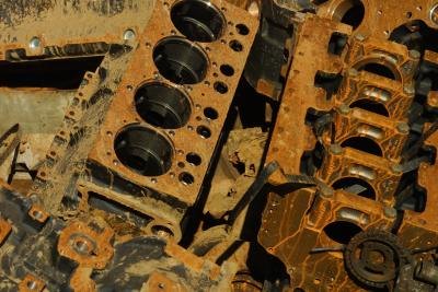
Some Nissan models - particularly the ZD30 Nissan patrol, have had a history of serious engine problems over the years, including piston cracks, head cracks and cracked cylinders and engine blocks. Nissan has taken steps to rectify the issues in recent years. If you have a cracked cylinder, that means that the recess in which the piston slides back and forth has become damaged, resulting in the air/fuel mixture leaking out around the piston. If it is the cylinder that is cracked, rather than the piston, you may have to replace the entire engine block.

Diagnosis and Troubleshooting

    A cracked cylinder will generally result in the loss of compression in that one cylinder. You may notice your engine "missing," running poorly and lacking in power. If your car runs at all, you would notice poor acceleration and poor performance on hills. However, there are a number of other issues that could cause this same problem. You may want to check your spark plugs for proper gapping and functioning. Also check your fuel injection system and your head gasket. Each of these items is much less expensive to repair, and would cause similar symptoms, so rule each of these out before replacing the cylinder.

Parts

    If you determine that your engine problems are, in fact, the result of a cracked cylinder, and the crack is too severe to weld shut, you will need to replace the engine block itself. The cost of the engine depends on the year, make and model of your Nissan. Expect to pay between $1,800 and $2,000 for a fully remanufactured engine block. However, you may also be able to find a complete engine in the aftermarket for around a thousand to $1,500, depending on the make and model of your Nissan.

Labor

    Generally, auto mechanic shops have a shop rate prominently posted in the customer service area. This is the hourly rate that the mechanic charges, generally in addition to the diagnostic fee, if any. The mechanic will give you an estimate based on the shop rate, times a multiplier from an industry guide called "The Mitchell Book" that lists how much time it typically takes to do a repair. Expect to pay between 8 and 10 hours of labor charges to do a full engine swap, depending on the make and model of your vehicle, assuming there are no other repairs to do.

Master Cylinder

    It is possible that your mechanic is erring to your master cylinder. The master cylinder converts mechanical energy from your foot pressing down on the brake pedal into hydraulic energy, which is then distributed through the power steering system to your brakes, or to your clutch. You can get a new brake master cylinder for about $100-$120. For clutch master cylinders, expect to pay about $30 to $60 for the part. According to CarsDirect.com, the average cost of a brake master cylinder replacement is $200-$300, including labor.

Continue reading...

History of the Turbocharger

Tuesday, February 25, 2014 | Labels: , , , | 0 comments |
History of the Turbocharger

Engineers and designers who work with internal combustion engines have always sought new ways to produce more power and efficiency. This has driven a great deal of automotive engineering and was the driving force behind the development of the turbocharger. Since its initial application to aircraft engines, the turbocharger has been adapted to different uses and has become an important option for modern automakers.

Origins

    The first turbocharger design earned a patent in 1905 by Swiss engineer Alfred Bchi. It was intended for use on aircraft engines at a time when aviation was a developing field. During World War I, the French military used turbochargers on many of its planes. Turbocharging solved many of the problems associated with high altitude flying by forcing air into the engine, thus negating the effects of the thinner atmosphere and lower oxygen content.
    Throughout the 1920s and 1930s, aviation technology continued to grow and turbochargers became common equipment on most advanced planes. This made it possible to design planes that could fly higher and run more efficiently (theore making them able to stay airborne longer).

Operation

    Turbochargers were developed to solve one of the primary needs of the internal combustion engine: that of feeding air, along with fuel, into the engines combustion chambers. While this air and fuel mixture is compressed during the engines compression cycle, feeding air that is more dense into the engine produces a boost in power. Turbochargers do precisely this, compressing the air in a process known as forced induction. In opposition to superchargers, which were developed later and compress air using energy from the engine itself, turbochargers are powered by the engines exhaust, thus making use of what would otherwise be lost energy.

Turbocharged Cars

    Cars became a natural place for turbochargers to be used once they had been proven on aircraft. As early as 1938, some automakers experimented with turbocharging their diesel engines, to mixed results. Turbochargers remained a mainstay on aircraft engines while only being sporadically offered on cars through much of the 20th century. In the 1950s and 1960s, turbochargers became a popular item for various racing circuits in the United States. The power boost achieved by turbochargers led to regulations of the technology and, in some cases, bans on the use of turbochargers to ensure fair competition.
    In 1962, General Motors became the first American automaker to offer turbochargers on its street cars, offering it on the Chevrolet Corvair and the related Oldsmobile Cutlass.

The Turbo Era

    The late 1970s and early 1980s became known as the "Turbo Era" in Formula 1 racing. This was due to the explosion in the popularity of turbochargers, with many race teams investing a great deal of money into the development of turbochargers that would give them a competitive edge. Some F1 races during the Turbo Era saw an entire field of turbocharged cars in competition. Race officials were quick to regulate turbochargers, placing limits on how much power they could be engineered to provide. Safety became a key concern, and the interest in the technology dropped off sharply. By the mid-1980s, turbochargers were banned altogether and race teams were forced to look elsewhere for improvements to their cars.

Recent History

    Turbochargers received some renewed interest during the Energy Crisis of the 1970s. Besides turning to smaller cars with more modest, fuel efficient engines, automakers began searching for ways to improve efficiency of their existing fleets. Turbocharged cars with four-cylinder engines were often sold alongside V-6 and V-8 models in the 1980s, often with the turbo versions sporting the highest performance ratings.
    Turbochargers also began to appear in other vehicles, such as motorcycles. In the case of motorcycles and sports cars, the light weight of a turbocharger makes it an attractive option for adding power as opposed to the addition of a large, heavy, expensive engine with greater displacement.
    The rise in energy prices in the 2000s only served to continue the advancing trend of turbochargers, seeing them appear in many cars, including small coupes and entry level models.

Continue reading...

Purpose of Exhaust Manifold

Thursday, January 30, 2014 | Labels: , , , | 0 comments |
Purpose of Exhaust Manifold

In an internal combustion engine, the exhaust manifold collects the products of combustion (exhaust gases) from two or more cylinders and conducts these to a single exhaust pipe.

Design

    Typically made of stainless steel, cast-iron or heavy-gauge steel, the exhaust manifold directs exhaust gases from multiple cylinders to a single exhaust pipe. In so doing, the exhaust manifold also helps to minimize leakage of heat, air and gases. Copper gaskets connecting the manifold to the cylinder heads can be used to create a more airtight system, though these are not necessary.

Benefits

    By minimizing the loss of heat, the exhaust manifold reduces the temperature under the hood. This helps to prevent overheating and damage to heat-sensitive parts while increasing power by reducing the temperature of the intake manifold. As gases move more quickly in higher temperatures, the exhaust manifold helps to increase the speed at which exhaust leaves the system.

Limits

    As cylinders fire at different times, an ideal exhaust manifold would contain pipes of different lengths to ensure that exhaust gases from one cylinder have been cleared from the system before another fires (i.e., to prevent back pressure). Due to space limitations, however, exhaust manifolds typically contain short pipes of uniform length. Though compact, this design increases back pressure, subsequently increasing heat loss under the hood and reducing engine performance.

Continue reading...

What Is the Purpose of a Crankshaft Sensor

Tuesday, January 28, 2014 | Labels: , , , , , , , | 0 comments |
What Is the Purpose of a Crankshaft Sensor?

Sophisticated computers that continuously adjust critical engine parameters control almost all modern car and truck engines. The crankshaft sensor is one of the numerous sensors that feed information to the computer.

Function

    The crankshaft sensor sends information to the engine computer about the precise position and speed of the crankshaft. Because the crankshaft is attached to the pistons, information about its position allows the computer to determine the relative positions of all critical engine components, including pistons, belts and valves. This makes it possible to time the injection of fuel and the spark plug ignition for optimum performance and fuel economy.

Principle of Action

    The crankshaft sensor consists of a metal disk positioned on the crankshaft and a detector that covers a magnetic coil. The metal disks movement past the coil causes a disturbance in the magnetic field, creating a stream of electric pulses that the computer uses to determine the speed and position of the crankshaft. The sensor does not produce direct data about the location and speed of the crankshaft; it sends raw data to the engine computer, which then calculates the desired values.

Malfunction

    A malfunctioning crankshaft sensor can cause various disturbances including extended crank time during start-up, rough running, bucking, compromised fuel economy and stalling. If your vehicle is equipped with an on-board diagnostic computer, a malfunction of the crankshaft sensor will trigger an error code to inform you about the problem.

Continue reading...